



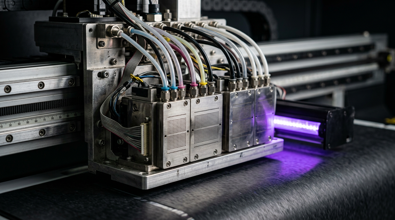
Direct answer: A piezo inkjet printhead ejects ink by changing the shape of a piezoelectric actuator in response to an electrical signal. That movement changes pressure in an ink chamber and ejects a droplet through a nozzle. The exact actuator, ink path and control waveform are specific to the printhead design.
Inside the Head
| Component | Role | Important detail |
|---|---|---|
| Nozzle | Opening through which ink exits. | Contamination or drying may affect jetting. |
| Ink chamber | Holds ink near the actuator. | Its geometry is part of the head design. |
| Piezo actuator | Moves when driven electrically. | Its movement changes pressure in the chamber. |
| Drive electronics | Apply controlled firing signals. | Settings and waveforms are model-specific. |
| Ink supply | Provides compatible ink under specified conditions. | Pressure, filtration and temperature depend on the system. |
From Electrical Signal to Droplet
- The controller schedules a firing event for the required image position.
- An electrical signal changes the piezo actuator shape.
- Actuator motion changes pressure in the ink chamber.
- Ink is ejected through the nozzle as a droplet when conditions support jetting.
- The system recovers and supplies ink for subsequent firings.
This is a simplified model; actuator movement and pressure waveforms vary between head families.
Piezo Versus Thermal Inkjet
Piezo inkjet uses actuator movement. Thermal inkjet uses a different ejection mechanism involving a heated element and bubble formation. The two are not interchangeable: ink compatibility, operating conditions and service requirements must be checked for the exact device.
Nozzle Check, Missing Lines and Deflection
A nozzle check makes individual nozzle behaviour easier to inspect. A missing mark can indicate a nozzle is not jetting; a displaced mark may indicate deflection. Causes can include dried ink, contamination, air, damaged components or supply issues. A test pattern is a starting point, not proof of one particular cause.
Resolution, Drop Size and Passes
Resolution describes spatial output; droplet size describes the volume of individual drops; and passes describe how output is built up as the print system scans or advances. These are different concepts. The best quality and speed setting depends on the head, substrate, ink, RIP and machine calibration.
White Ink and Recirculation
White pigment ink can settle, so some systems use agitation or recirculation as specified by the manufacturer. Recirculation is not universal and does not remove the need for maintenance. Ricoh describes a specific recirculating textile printhead in its published product information; do not assume all heads use the same path.
Safe Care and Service
- Use only the ink and cleaning fluids approved for the installed system.
- Follow the documented nozzle-check, capping and shutdown procedure.
- Do not force liquid through a head or touch delicate nozzle surfaces without authorised instructions.
- Stop and contact a qualified engineer for electrical faults, leaks or persistent jetting failure.
Inside a Piezo Printhead: The Complete Ink Path
A piezoelectric inkjet printhead converts controlled electrical signals into tiny droplets. It does not paint by dragging a brush across the surface. A print file is processed by the RIP and printer electronics into instructions that determine when selected nozzles should fire as the printhead and substrate move relative to each other. The resulting dots build the image gradually.
The head is only one part of the system. Ink must arrive in a suitable condition, at the pressure and temperature expected by the design. A carriage or other motion system must position the head, and the media feed or bed must position the material. Software coordinates these elements. A problem in any one part can look like a printhead problem, so a sensible diagnosis considers the entire path.
In a typical system, ink travels from a reservoir through a supply path that can include tubes, filters, dampers or a recirculation circuit. The exact arrangement is model specific. Inside the head, ink is distributed towards small chambers associated with nozzles. An actuator changes a chamber’s shape or volume when driven electrically. That change creates a pressure disturbance in the ink, and an appropriately shaped drive pulse can eject a drop through the nozzle opening.
This description is a simplified functional model, not a service diagram for every head. Some heads share fluid channels or use different actuator arrangements. Consult the equipment manufacturer’s documentation before working on any ink path, electrical connection or head assembly.
The Firing Cycle, Explained Step by Step
- Ink supply: Compatible ink reaches the printhead through the machine’s approved supply system. The supply must be stable enough for the particular head and operating mode.
- Signal: The printer sends an electrical drive waveform to selected actuators. A waveform is more than an on/off switch: its shape and timing affect how the fluid responds.
- Actuator movement: The piezoelectric element changes shape in response to the electrical drive. Depending on the design, this movement deforms a wall or another part of the ink chamber.
- Pressure wave: The chamber movement produces a pressure change in the liquid. When the system is designed and driven correctly, this pushes ink towards the nozzle and forms an ejecting liquid jet.
- Drop formation: The jet separates into a droplet in flight. Unwanted smaller satellite drops or unstable trajectories can affect the result, depending on the ink, waveform and conditions.
- Refill and recovery: Ink returns to the required condition for a subsequent firing. The time available for this process affects how the system behaves at production speeds.
- Placement: The droplet travels across the head-to-media gap and lands on the substrate. Motion, timing, media condition and surface behaviour all influence where the final dot appears.
These events happen many times during printing. They are governed by the head and printer design, not by one universal setting. Operators should not modify drive voltages or waveforms unless the machine manufacturer explicitly authorises the procedure. An incorrect setting can reduce print quality or damage equipment.
Why Ink Properties Matter
Ink is an engineered fluid, not simply coloured water. Viscosity affects how easily it flows. Surface tension influences how the liquid behaves at the nozzle and on the substrate. Pigment particle size and stability, additives, evaporation rate and other properties also matter. The acceptable operating window is specific to the head and the complete ink system.
A fluid that looks similar to the existing ink is not necessarily compatible. It may behave differently in seals, tubing, dampers, filters or the printhead. Mixing unknown formulations can cause precipitation or other problems. Use the printer and ink supplier’s documented compatibility guidance, including any approved procedure for changing formulations.
Storage and handling also affect performance. Keep containers labelled and follow the ink manufacturer’s storage, shelf-life and safety guidance. If a batch is suspected, record the product identity and batch information rather than immediately changing several components. Check the safety data sheet for handling and disposal requirements.
What Do Nozzles Actually Do?
A nozzle is a small opening through which ink leaves the head. A head contains a pattern of nozzles, with the number, arrangement and colour-channel configuration varying by model. During a nozzle check, the printer fires a defined pattern so that gaps or displaced marks can be compared with the manufacturer’s example.
A missing segment suggests that the relevant nozzle or group of nozzles may not be producing the expected mark. It does not identify the cause by itself. Possible explanations include dried ink, contamination, an air or supply problem, a maintenance station issue, an electrical fault or head damage. The pattern can also be difficult to interpret on unsuitable media, with low contrast or after a handling error.
A deflected nozzle can fire but deposit ink away from the expected position. This may appear as a displaced line or dot in the approved test. Deflection is different from a completely missing mark, but both can contribute to visible defects. Save a dated pattern before and after an authorised intervention so that changes can be compared rather than guessed.
Droplet Size, Resolution and Print Passes
Droplet size describes the volume of an individual drop. Some systems support different drop volumes through their design and control waveform; others have different capabilities. Smaller drops can support fine detail and smoother tonal transitions in a suitable workflow, but droplet volume alone does not guarantee better output. Ink spreading, substrate coating, head condition and the RIP all contribute.
Resolution describes spatial sampling or output density, often stated in dots per inch. A quoted resolution is not the same as the number of physical nozzles, and it should not be treated as a direct measure of the quality of every image. The effective result depends on the print mode, motion, jetting, ink and media.
A pass describes part of the way a scanning system builds an image through repeated sweeps and media advances. Depending on the printer and mode, additional passes may reduce the visibility of some defects while changing productivity. They do not repair a missing nozzle or make an incompatible ink suitable. Compare modes on the actual substrate and approve a physical sample for the customer’s intended viewing distance.
For a practical comparison, print the same small test artwork using the same ink, substrate and profile while changing only the approved print mode. Record the mode, nozzle condition and observed detail. Evaluate banding, fine lines, solid areas and drying or curing according to the ink system. Avoid comparing a new mode against an old sample if several other variables changed.
Head-to-Media Gap and Drop Placement
The gap between the nozzle plate and the substrate affects the distance a droplet travels before landing. A greater gap can make accurate placement more difficult in some conditions, while too little clearance increases the risk of a head strike. Actual permitted heights depend on the head, printer, substrate and fixture. Some systems are designed specifically for a larger gap; do not apply a generic clearance number to every machine.
Before printing, check for curled edges, wrinkles, raised seams, warped boards or loose fixtures using the machine’s approved procedure. The highest point of the item matters, not just its average thickness. If material rises into the head path or a strike occurs, stop safely and follow the manufacturer’s instructions. A strike can affect alignment, damage the nozzle plate or cause other issues that cannot be diagnosed from appearance alone.
Piezo and Thermal Inkjet: What Is Different?
Both technologies can eject ink droplets, but the actuation mechanism differs. Piezo inkjet uses an electrically driven piezoelectric element to create the pressure change. Thermal inkjet uses a heater to generate a vapour bubble that helps eject ink. This is a description of the mechanism, not a claim that all printers of one type are better for every application.
Each device is designed around a particular ink and operating system. Cartridge design, service approach and compatibility differ by manufacturer. Do not transfer an ink, cleaning fluid or maintenance procedure from one technology to another simply because both are called inkjet printers. Review the actual equipment’s documentation and supplier support.
White Ink and Recirculation
White inks commonly contain pigment that can settle during storage or idle periods. Some machines use agitation, circulation or another manufacturer-designed approach to maintain the ink in a usable condition. The arrangement varies: a system may circulate ink through part of the supply path, and not every head recirculates ink at the nozzle. Ask the supplier to explain the configuration installed in your machine.
Follow the approved preparation and maintenance schedule for the exact white ink. Do not shake a container, open a circuit or alter circulation settings unless its instructions permit it. Record periods of inactivity and any symptoms. Circulation can support consistent supply in a system designed for it, but it does not remove the need for nozzle checks, correct shutdown or regular maintenance.
Common Symptoms and a Logical First Check
| Symptom | Possible areas to investigate | First safe action |
|---|---|---|
| Gaps in the nozzle pattern | Nozzle condition, supply, maintenance station or electrical system | Save the pattern and follow the approved recovery sequence. |
| Displaced marks | Deflection, nozzle condition or pattern interpretation | Compare with the manual and repeat the test on suitable media if instructed. |
| Fine vertical lines appear doubled | Head alignment, movement or print mode | Check nozzle condition and run the model-specific alignment test. |
| Horizontal bands | Nozzles, feed, alignment, print mode or ink supply | Record the pattern and compare a nozzle check before adjusting settings. |
| Colour changes | Jetting, ink, profile, media or viewing conditions | Compare with a documented approved sample and check for recent changes. |
| Sudden fault after a head strike | Potential mechanical, head or alignment damage | Stop safely and request qualified inspection. |
The table is a starting point, not a diagnosis. Several faults can produce similar results, and more than one fault can occur at the same time. It is especially important not to replace a head solely because a print shows banding. Preserve the evidence and use the manufacturer’s diagnostic sequence.
A Practical Diagnostic Workflow
- Define the problem. Identify the affected colours, the job, when the symptom began and whether it appears throughout the print or in a particular area. Note error codes exactly as displayed.
- Record the configuration. Capture the printer and head model, ink product and batch where available, substrate, print mode, RIP preset and recent service history. Do not include customer artwork or passwords unnecessarily.
- Check the basics. Confirm approved media loading and visible operating conditions without opening guarded areas. Look for obvious wrinkles or material movement and stop if there is a clearance hazard.
- Print the approved nozzle check. Use the media and method specified for the machine. Compare the result against the manufacturer’s instructions, not a pattern from a different model.
- Follow authorised recovery. If the manual recommends cleaning, use the specified routine and observe any limits or wait times. Repeated aggressive cleaning consumes ink and may not resolve an underlying fault.
- Re-test and compare. Mark the date and action on each print. If the pattern improves, worsens or remains unchanged, that evidence helps decide the next step.
- Isolate other variables. If jetting is acceptable but the defect continues, investigate model-specific alignment, media advance, profile or substrate factors as appropriate. Change one authorised setting at a time and retain the original value.
- Escalate. For leaks, electrical errors, recurring failures, a head strike or any work beyond operator training, stop and involve an authorised technician. Share the test prints and service record.
This sequence reduces guesswork. It does not replace the manufacturer’s instructions, which may prescribe a different order for a specific machine or ink. When the result is uncertain, avoid making multiple changes before the service engineer can see the original condition.
Maintenance, Cleaning and Shutdown
The printhead’s maintenance station can include a cap, wiper and waste-ink path, depending on the printer. These components help support normal cleaning or parking, but their precise functions and service intervals vary. Follow the machine’s maintenance schedule and use only approved tools and fluids. A dirty or damaged maintenance component can affect jetting, but it should be assessed under the manufacturer’s procedure.
Shutdown is a process, not just switching off a power strip. Where the manufacturer requires it, use the printer’s normal shutdown sequence so the carriage can park or cap correctly. For planned inactivity, ask the supplier about storage preparation and restart checks. Requirements differ substantially between ink chemistries and machine designs.
Never force cleaning fluid through a head, scrape the nozzle plate or disconnect ink or electrical lines as an improvised fix. Some service operations involve moving machinery, electricity, chemicals or UV exposure. Keep guards and interlocks in place, follow the safety data sheets and leave restricted work to trained personnel. If a leak is present, stop the machine safely and use the documented response.
When Is Replacement Actually Justified?
A printhead is a costly component, so replacement should follow evidence rather than a single defective print. A service engineer may evaluate test patterns, maintenance condition, the ink supply and authorised diagnostics. The exact checks depend on the machine, warranty and service policy. Persistent failure after approved troubleshooting may justify a repair or replacement decision, but neither outcome can be guaranteed from a remote symptom description.
Before authorising work, request a written explanation of the findings, proposed part, compatibility, labour and warranty terms. Ask whether related components need inspection and what test will demonstrate acceptable operation after service. Keep the old test patterns and the service report with the machine record.
Operator Checklist for Consistent Results
- Use the ink, media and maintenance materials approved for the installed configuration.
- Check the nozzle pattern at the interval recommended by the manufacturer and before colour-critical work where appropriate.
- Use documented loading, clearance and shutdown procedures.
- Keep a sample and settings record for repeat jobs.
- Investigate changes in material, ink, environment and settings before assuming head failure.
- Do not bypass guards or perform restricted service work.
- Record each authorised action and compare the result before changing another variable.
Related Troubleshooting Guides
Continue with nozzle dropout and clogging diagnosis, ink supply components and printhead alignment checks. These topics are connected, but each requires its own test and model-specific procedure.
Sources and Further Reading
See Epson on piezoelectric printhead technology and Ricoh printhead recirculation details. Specifications must be checked against the installed model.
Frequently Asked Questions
How does a piezo printhead eject ink?
An electrical signal moves a piezoelectric actuator, changing pressure in an ink chamber and ejecting a droplet through a nozzle.
Are piezo and thermal inkjet heads the same?
No. They use different droplet-ejection mechanisms and have model-specific ink and operating requirements.
What is a nozzle check?
It is a test pattern used to inspect nozzle jetting. Missing or displaced marks can help identify a problem, but further diagnosis is needed.
Does a missing nozzle always mean the head must be replaced?
No. Drying, contamination, air or supply faults are possible causes. Follow the approved recovery procedure and consult a qualified engineer before deciding.
What is nozzle deflection?
A nozzle may eject a drop away from the intended path, causing a displaced mark in a test pattern or visible print defects.
Does every white-ink system circulate ink?
No. Some designs use circulation or agitation; follow the specific machine and ink manufacturer instructions.
Can I use any ink in a piezo printhead?
No. Use ink specified as compatible with the exact head and machine; different ink chemistries and formulations are not automatically interchangeable.
