



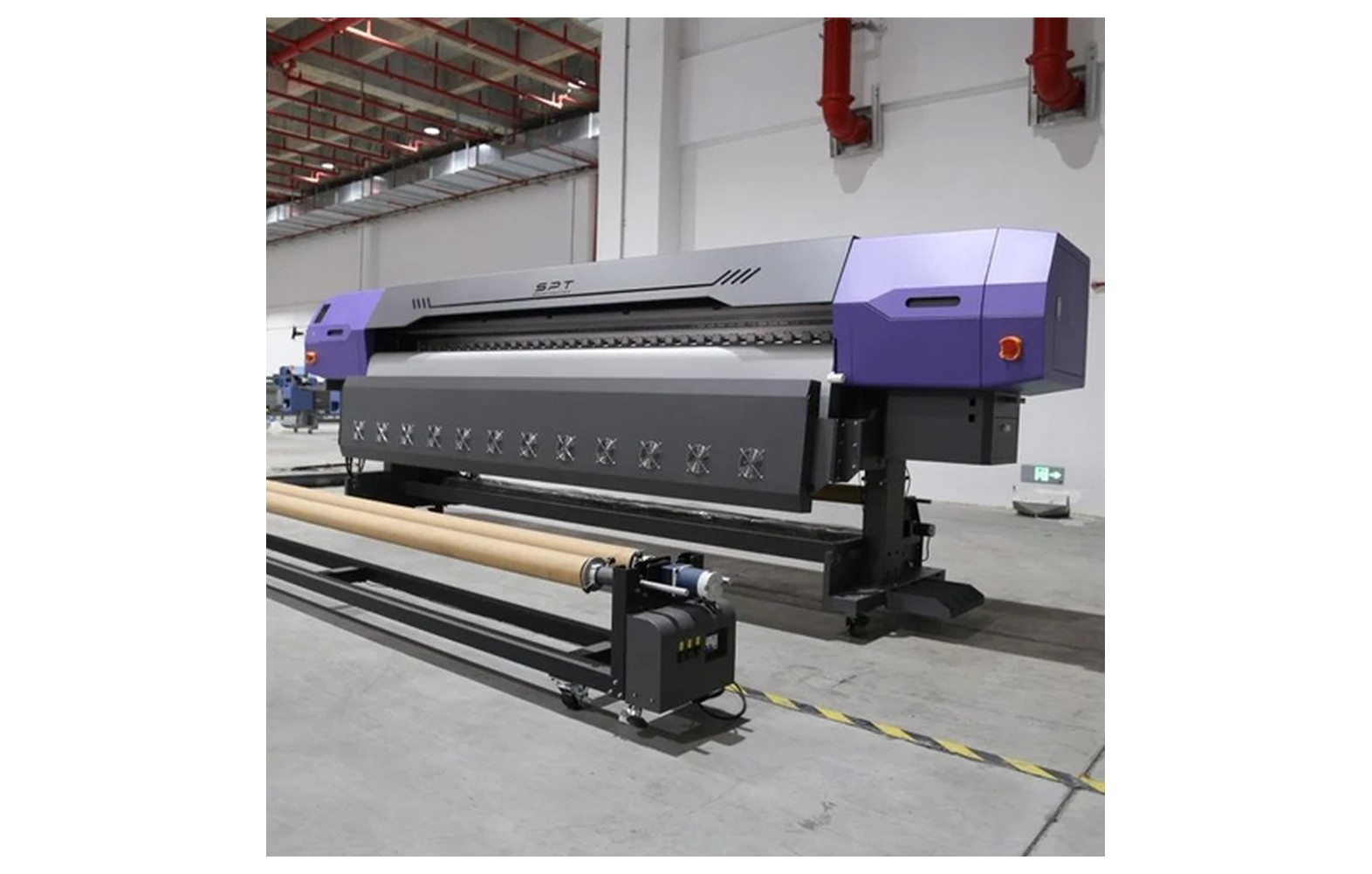
Direct answer: A digital inkjet machine is a coordinated system: software turns artwork into firing instructions; the controller synchronises printhead firing with motion; ink delivery supplies the head; and a feed or bed positions the substrate. Drying or curing depends on the ink and machine. This guide focuses on industrial inkjet equipment, not toner-based digital presses.
The Complete System Map
| Subsystem | Function | Failure symptom |
|---|---|---|
| RIP and controller | Convert and schedule print data. | File, colour or communication errors. |
| Ink delivery | Move compatible ink through the specified supply path. | Air, contamination or unstable supply can affect jetting. |
| Printhead | Eject small drops through nozzles. | Missing nozzles or deflection may cause streaks. |
| Motion and position sensing | Move or track the carriage and substrate. | Misalignment, feed error or inconsistent placement. |
| Media handling | Support and advance material or hold an item on a bed. | Skew, head clearance problems or registration errors. |
| Drying or curing | Process printed ink using the system designed for it. | Smearing, tackiness or inadequate adhesion. |
1. Artwork, RIP and the Controller
The RIP prepares artwork for a particular printer, ink and substrate. Depending on the system it manages colour conversion, print layout, print mode and special layers such as white. The controller coordinates data, firing and motion. A file can look correct on a screen yet print differently if the chosen profile or media setting is wrong.
2. Ink Supply and Printhead
A typical supply path includes ink containers, tubing and components such as filters or dampers, but the layout varies by machine. Ink and cleaning fluid must match the printhead and the machine manufacturer requirements. The head ejects droplets; nozzle condition and stable ink supply matter to consistent output. White pigment ink may need a manufacturer-specified circulation or agitation system.
3. Carriage, Rails and Position Feedback
In a scanning machine the carriage moves across the substrate while printing; the media advances or the bed moves between passes. Position feedback can use an encoder strip or other sensors. A dirty encoder, mechanical play, feed calibration error or blocked nozzles can all produce visible defects, so diagnose the symptom rather than assuming a single cause.
4. Media Handling and Surface Support
Roll printers use feed, tension and take-up arrangements suited to flexible media. Flatbeds support rigid items on a bed, often using fixtures or a vacuum system. Check material thickness, flatness and head clearance before printing. A rotary attachment for cylindrical objects is model-dependent and must be supported by the printer and its software.
5. Drying, UV Curing and Finishing
Solvent and water-based systems dry according to the ink and media; UV-curable ink requires the specified curing system. Do not assume touch-dry means ready for lamination or that every substrate accepts every ink. Follow the ink, media and equipment instructions, and test adhesion and final performance on the actual item.
6. Utilities and Safety
Power, earthing, temperature control, ventilation, compressed air and cooling are installation-specific. Not every printer requires a compressor or chiller. Have a qualified installer check nameplate ratings and site requirements. Isolate power before authorised maintenance; never bypass guards or interlocks.
Practical Diagnostic Sequence
- Record the job, media, print mode and error message.
- Run the manufacturer nozzle check and inspect the approved test pattern.
- Check media loading and permitted head clearance.
- Compare the saved RIP preset and ink or media specifications.
- Escalate persistent faults to a qualified service engineer rather than forcing a repair.
Sources and Further Reading
Epson explains scanning and stationary linehead designs in its PrecisionCore linehead overview. Review your specific machine manual for the actual configuration and service instructions.
From a Digital File to a Finished Print
An inkjet printing machine turns a digital design into controlled droplets on a physical surface. It does this through several coordinated subsystems, not through the printhead alone. The artwork must be prepared for the printer, ink must reach the nozzles, motion must position the head and material, and the deposited ink must be processed appropriately for the application.
In a scanning printer, a carriage usually moves the head across the material while the printer advances the media or moves a bed according to its design. Other architectures use a different arrangement. The controller coordinates firing with position information so droplets are placed where the processed image calls for them. The exact mechanism and available checks are model specific.
Understanding these subsystems helps an operator describe a problem and avoid unnecessary part replacement. It does not authorise electrical work, opening the ink path or overriding guards. For maintenance and safety, use the manufacturer documentation for the installed machine and ink.
1. Artwork and the RIP
Artwork can contain vector shapes, text, photographs and other raster elements. The design must be prepared at the intended size with suitable image detail and the correct file handling for the job. A picture that looks sharp on a phone may not contain sufficient detail for a large print viewed closely.
The raster image processor, or RIP, interprets the file and prepares output instructions for the printer. Depending on the system, it manages layout, colour conversion, print mode and special layers such as white. A saved preset may combine a media setting, profile, pass mode and other controls. The available options depend on the printer and software.
An ICC profile is associated with a particular colour workflow and should be used according to the RIP provider’s instructions. Changes in ink, material or print mode can change the result. A profile cannot compensate for missing nozzles, a head strike or an unsuitable substrate. For repeat work, retain a physical proof and a record of the artwork version, printer, ink, media and settings.
2. Controller and Electronics
The controller receives prepared job data and coordinates machine functions. Depending on the design, it manages communication with the RIP, printhead firing, carriage movement, media positioning, sensors and other machine functions. Firmware and configuration connect these elements to the particular hardware.
An error displayed at the control panel is useful evidence, but the wording of an error does not always identify a replaceable part. Record the exact message, when it appeared and what the machine was doing. Use the manufacturer’s troubleshooting instructions and contact a qualified engineer for internal electrical checks or recurring faults.
Do not bypass interlocks, open electrical enclosures or change service parameters because a generic video suggests a fix. Moving machinery and electrical energy can create serious hazards. Follow the site’s isolation procedures and the manufacturer’s service instructions for work beyond normal operator access.
3. Ink Storage and Delivery
Ink is held in a cartridge, tank or other container and supplied to the head through a machine-specific path. Depending on the printer, this path may include tubing, filters, dampers, pumps, valves and circulation. A pump used during cleaning is not necessarily the same component as one used for ink circulation.
The ink must be suitable for the complete printer system, not just a head family mentioned in an advertisement. Fluid properties, seals, tubing, filters, maintenance materials and operating conditions all matter. Use approved ink and cleaning fluids. Do not mix formulations, force fluid through a head or open an ink line without the manufacturer’s authorised procedure.
Some white-ink systems use agitation or circulation to help manage pigment distribution. The route and purpose differ by machine. A system that circulates ink in a reservoir does not necessarily circulate it through the head. Ask the supplier to explain the installed configuration and follow its handling and idle-period instructions.
4. Printhead and Nozzles
The printhead ejects droplets through nozzles. In a piezo inkjet head, an electrically driven actuator creates a pressure change that helps form a drop. Other inkjet technologies use different mechanisms. In both cases, the head operates as part of a wider system of compatible ink, electronics, motion and maintenance.
A nozzle check prints a machine-specific pattern used to inspect jetting. Missing or displaced marks can help identify a symptom, but do not prove that the head is permanently damaged. Drying, contamination, supply conditions, maintenance-station issues and physical or electrical faults are among the possibilities.
Save a dated test before and after an approved maintenance action. Follow the recommended cleaning sequence and its limits. Repeated aggressive cleaning may consume ink and create waste without resolving the cause. If the issue persists or work requires restricted access, involve a qualified service engineer.
5. Carriage, Rails and Position Feedback
On a scanning printer, the carriage carries the printhead assembly across the material. Rails or guides support and direct its motion. Motors, belts or other mechanisms drive movement, while a position feedback system helps the controller coordinate the carriage and droplet firing. The design varies by printer.
An encoder strip or another sensor may provide position information. If the movement or feedback system is not functioning correctly, symptoms can include misplacement, uneven lines or a machine error. However, a visible defect does not identify one component by itself. Alignment, media condition, jetting and the file can also matter.
Operators should perform only the inspection and cleaning described in the user manual. Do not touch or clean a sensitive encoder strip with an unapproved material, manually force the carriage or adjust rail components without training. For unusual noise, obstruction or a motion error, stop safely and contact service.
6. Roll Media Feed and Take-Up
A roll-to-roll printer must support the roll, position the media and advance it consistently through the print area. Depending on its design, it may use pinch rollers, feed rollers, guides, a platen and an optional take-up system. Loading and tension are important, but the correct arrangement depends on the specific machine and material.
Incorrect loading, a damaged roll, unsuitable material or a feed problem can contribute to skew, wrinkles, banding or registration problems. Before changing calibration values, inspect the normal operator-accessible loading points and compare the situation with the manual. Stop if a raised edge or wrinkle threatens the head.
Media-feed calibration assesses advance using the printer’s approved procedure. It is distinct from printhead alignment and, where applicable, print-and-cut registration. Use the actual production material and documented mode as instructed. Record the original setting before any authorised change and verify the result on a representative sample.
7. Flatbed, Vacuum and Fixtures
A flatbed printer supports rigid sheets or items on a bed. Some beds use vacuum zones to help hold suitable material in place; others use different hold-down arrangements. An object may also require a manufacturer-approved fixture or jig. The method depends on item shape, material, bed design and print clearance.
Porous, warped or irregular items can be difficult to hold securely. Vacuum does not guarantee that every item will stay flat, and an improvised fixture can create a collision hazard. Use only arrangements approved for the machine. Check the highest point of the item and any fixture using the manufacturer’s height and clearance procedure.
If material lifts or moves, stop and investigate using the manual. Zone selection, surface condition, material suitability, leaks or equipment faults are possible factors. Do not assume the pump is defective or cover bed areas in a manner not authorised by the manufacturer.
8. Maintenance Station and Waste Path
Many printers include a maintenance station with a cap, wiper and a system for handling waste ink, although the exact components and functions vary. These parts support the printer’s approved maintenance and parking routines. Their condition can influence jetting, but an operator should not assume that every missing nozzle originates there.
Use the normal shutdown sequence so the machine can complete any required parking or maintenance action. For extended inactivity, ask the manufacturer about the specific storage and restart procedure. Maintenance intervals depend on the printer and ink, so a generic online schedule is not a reliable substitute.
Check waste capacity and replace operator-serviceable consumables only as instructed. Ink and cleaning materials can present chemical hazards. Consult their safety data sheets, wear the required protection and follow site and local disposal procedures.
9. Drying, UV Curing and Transfer Processes
Printed ink must be processed in a way that suits its formulation and application. Some systems rely on drying; UV-curable inks require a compatible curing system. DTF production also involves a compatible film, powder, curing and transfer workflow. These processes are not interchangeable.
A dry-feeling UV print does not alone prove complete cure or suitability for a particular use. Adhesion is a separate property that depends on the material, preparation, ink and process. Agree appropriate test methods and acceptance criteria with suppliers and the customer. Do not promise food-contact, dishwasher or outdoor suitability without evidence for the complete application.
UV equipment can expose operators to hazards if its protective systems are defeated. Keep guards and interlocks in place, follow the manufacturer’s safety instructions and leave lamp or electrical servicing to qualified personnel. For DTF and other chemical processes, follow the relevant safety data sheets and ventilation guidance.
10. Utilities, Environment and Workshop Setup
The machine’s nameplate and installation manual define its electrical requirements. A qualified electrician should assess the supply, protective devices and earthing against the actual equipment and applicable local requirements. UPS or stabiliser selection must consider the manufacturer’s guidance and the loads involved; a single generic sizing multiplier is not a substitute for engineering assessment.
Temperature, humidity and dust can influence media handling, ink behaviour and print consistency. Maintain conditions within the equipment and ink suppliers’ specified ranges. Ventilation and extraction should be assessed for the processes, chemicals and site; use supplier documentation and qualified advice rather than assuming one fan arrangement is suitable for all machines.
Provide adequate space for loading, maintenance and safe access. Train operators on emergency stops, chemical handling and the procedures they are authorised to perform. The correct setup depends on the printer, facility and materials used.
How the Subsystems Interact During a Job
- Prepare the job: Confirm artwork dimensions, material, colour requirements and the intended end use.
- Check the printer: Use the manufacturer-approved nozzle check and normal pre-operation checks. Record any warnings or unresolved faults.
- Load the substrate: Follow the machine’s instructions for a roll, sheet or fixture. Check clearances and secure hold-down.
- Select the workflow: Choose the documented RIP preset, profile, mode and any white layers for the actual configuration.
- Print a proof: Produce a representative sample and check detail, colour and registration under agreed conditions.
- Process and inspect: Follow the applicable drying, curing or transfer instructions and agree relevant end-use tests.
- Record the result: Save the approved sample and settings, including any authorised changes, before running the full job.
For a repeat order, compare the current configuration with the saved record. A change in substrate, ink batch, RIP preset or nozzle condition can affect the result. If the job differs from the proof, change one authorised variable at a time and document the outcome.
Where to Start When Print Quality Changes
| Symptom | Possible subsystems | Starting point |
|---|---|---|
| Missing or displaced nozzle marks | Head, ink supply or maintenance system | Keep the test and use the approved recovery sequence. |
| Horizontal bands | Jetting, feed, alignment or print mode | Record the defect and check the nozzle pattern before adjustments. |
| Skew or wrinkling | Media, loading, feed or take-up | Stop if clearance is at risk and inspect operator-accessible loading. |
| Colour differs from proof | Ink, jetting, profile, substrate or viewing conditions | Compare the recorded job configuration and physical reference. |
| Material lifts on a flatbed | Substrate, hold-down, fixture or vacuum system | Stop safely and follow the approved hold-down procedure. |
| Smearing or poor adhesion | Ink processing, surface preparation or material compatibility | Review the complete process and agree an appropriate test. |
These are possible areas to investigate, not conclusions. Keep test prints, note changes and contact service for faults outside operator training. Do not replace a head, pump or controller solely on the basis of a single symptom.
Service Records and Supplier Questions
Keep one record for each machine with the model, serial number, installed configuration, approved supplies and relevant software. Add dated nozzle tests, maintenance actions, error messages and authorised repairs. Do not store passwords or unnecessary customer artwork in the operational log.
When buying or servicing equipment, ask which ink and media are approved, what routine tasks operators can perform, which work requires an engineer, and what tests are used after service. Request a demonstration using representative artwork and the actual material where practical. Compare output quality and finished-job throughput under documented conditions rather than relying on a single advertised speed or resolution figure.
Continue Learning
Explore piezo printhead operation, ink delivery components, banding diagnosis and service records. For any machine-specific setting, use the manufacturer’s documentation and qualified service support.
Frequently Asked Questions
What are the main parts of a digital inkjet machine?
The principal subsystems are the RIP and controller, ink delivery and printheads, motion and position sensing, media support or feed, and the drying or curing system. Exact components vary by machine.
Does every digital printer have a moving carriage?
No. Many serial inkjet printers scan a carriage across the media, while some linehead systems keep the head stationary and move the substrate.
Is a RIP the same as a printhead?
No. The RIP prepares print data; the printhead physically ejects droplets under control of the machine.
What does a damper do?
A damper is an ink-supply component used in some machines. Its purpose and replacement procedure depend on the machine design; use the manufacturer documentation.
Does every UV printer need a chiller?
No. Cooling requirements depend on the model and its curing and ink systems. Use the machine nameplate and installation manual.
Why does a printer produce banding?
Possible causes include nozzle dropout, feed calibration, print mode and motion errors. A nozzle check and manufacturer diagnostic procedure help narrow the cause.
What should I check before servicing the machine?
Follow the manufacturer safety procedure, isolate power where required, and use a qualified engineer for electrical or pressurised ink-system work.
