



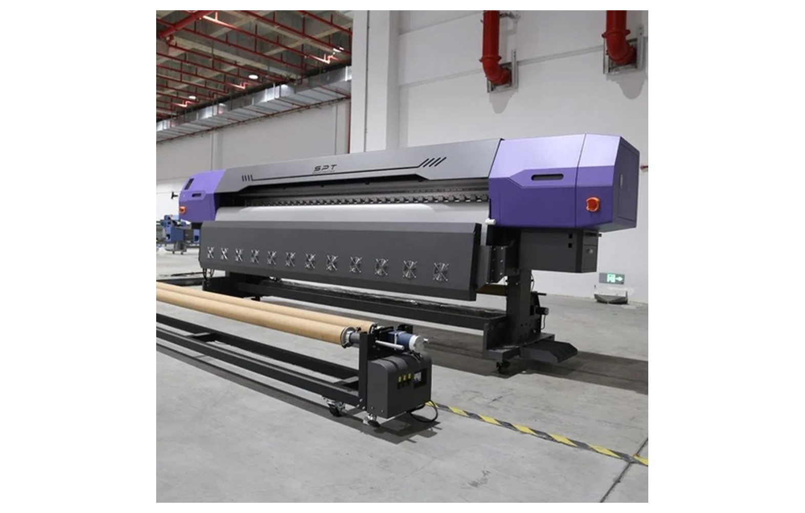
Direct answer: Banding is a visible pattern of unwanted stripes or density variation. It can arise from nozzle jetting, feed calibration, motion, print settings, ink, media or curing. A single visual symptom cannot identify the cause by itself.
Engineering Principles and Components
| Topic | Function | Practical check |
|---|---|---|
| Nozzle dropout | Missing jetting can leave light lines. | Run the approved nozzle check and preserve the result. |
| Feed or step error | Incorrect substrate advance can create repeated bands. | Check loading and follow the feed-calibration procedure. |
| Motion and registration | Carriage or position-feedback faults can affect placement. | Inspect according to the service manual. |
| Print mode or media | Incorrect settings or an unsuitable profile may change output. | Compare approved settings on the actual media. |
| Cure or drying | Ink processing can affect appearance and performance. | Follow ink, media and machine guidance. |
Practical Shop Checklist
- Record band direction, spacing, print mode and affected colours.
- Run a nozzle test before altering several settings.
- Repeat a controlled sample after one approved change at a time.
- Escalate persistent errors, head strikes or electrical faults to qualified service.
What Is Banding in Digital Inkjet Printing?
Banding is an unwanted visible pattern of stripes or repeating density differences in a print. Bands may appear lighter or darker than the surrounding area, affect one or several colours, or become most visible in a smooth gradient or solid fill. Their appearance depends on the printer, ink, material, image and viewing conditions.
Banding is a symptom, not a diagnosis. Missing or deflected nozzles, media advance, printhead alignment, carriage motion, ink supply, print mode and substrate behaviour can all contribute. A problem that appears after changing material may be related to that change, but the timing alone does not prove the cause.
A disciplined investigation starts with an approved test, a documented baseline and one authorised change at a time. This guide focuses on scanning inkjet printers. Procedures differ by model, so the equipment manufacturer’s manual and safety instructions take priority.
Record the Defect Before Changing Settings
Keep an affected print and label the direction in which the material travelled. Describe whether the bands cross the width or run along the direction of travel, whether they repeat regularly and whether they occur throughout the job or only in one area. Words such as horizontal and vertical can be ambiguous after the sheet is rotated, so recording the machine orientation is useful.
Note the affected colours, artwork, final size, material, ink, RIP preset, print mode, pass setting and any white layers. Record whether the defect appears in solid areas, gradients or photographs. If a customer has approved a previous sample, retain it for comparison under the same lighting and viewing conditions.
Record recent changes, including a new roll, ink container, profile, maintenance action, long idle period or machine move. A clear history helps the service provider select the right tests. Do not include passwords or unnecessary customer artwork in the service log.
How a Nozzle Fault Can Create Bands
A printhead contains nozzles that eject droplets according to the machine’s instructions. A missing nozzle may leave a gap in a test pattern; a deflected nozzle can produce a displaced mark. Depending on the print mode and image, these conditions may contribute to streaks, uneven coverage or colour changes.
Print the nozzle-check pattern specified for the exact machine, using the recommended media. Save the first test before cleaning. Compare it with the manufacturer’s example rather than a pattern from a different printer. Some patterns require particular media or viewing conditions to make all channels visible.
If the test is unsatisfactory, use only the approved recovery sequence and record the result. Missing marks can have several causes, including drying, contamination, supply problems, maintenance-station issues or physical and electrical faults. They do not automatically mean that a head must be replaced.
If the test appears normal, do not assume all possible faults are excluded. Continue with the manufacturer’s sequence for feed, alignment and other relevant checks. A nozzle check evaluates jetting under its test conditions; the production job can involve a different mode, coverage or material.
How Media Advance Can Affect Output
In a scanning printer, the image is built through carriage scans and controlled material or bed movement. If the advance differs from what the print mode expects, successive portions of the image may overlap or leave gaps, contributing to repeated density variations. The relationship depends on the printer’s interleaving and print mode.
Before changing a feed value, check that the material is loaded according to the manual. A damaged roll, unsuitable roller placement, wrinkles, slippage, take-up setup or substrate behaviour can affect movement. Stop safely if media rises into the head path or if a mechanical problem is suspected.
Use the manufacturer-approved feed-calibration pattern and procedure for the actual material and mode where instructed. Record the original setting and the selected result, then print a comparison. Do not copy a correction value from another machine or assume the same value works for every substrate.
Printhead Alignment and Carriage Motion
Printhead alignment concerns the placement of droplets relative to machine movement and, where applicable, other heads or scan directions. Some printers support bidirectional printing, in which the head fires while travelling in both directions. A model-specific alignment procedure helps assess whether the marks are placed as intended.
Alignment, feed and nozzle checks address different parts of the process. An alignment correction will not repair a blocked nozzle, and a feed adjustment is not a universal solution for doubled vertical lines. Follow the order in the printer manual, including any requirement to verify nozzle condition first.
The carriage drive, guide system and position feedback may also be relevant to placement. An encoder strip is used on some machines, but designs vary. Do not clean a strip with an unapproved fluid, adjust a belt or open a guarded area based on a generic troubleshooting video. Report errors or unusual motion to qualified service.
Print Mode, Passes and Direction
The RIP and printer can offer different combinations of resolution, passes, direction and other controls. A pass mode determines part of how the image is built, but manufacturers may define the setting differently. More passes can change the visibility of some defects and the production time. They are not a guaranteed repair.
For a controlled comparison, use the same artwork, ink, material, size and viewing conditions. Confirm normal nozzle condition and compare two manufacturer-supported modes. Record the mode, direction, pass setting and relevant profile. If a higher-pass sample looks better, investigate whether that mode is an acceptable production choice and whether an underlying fault still requires attention.
A profile or preset used for one print mode may not be appropriate for another. Follow the RIP and profile provider’s guidance. Approve a physical sample on the actual substrate rather than relying on a screen preview or an advertised DPI number.
Ink Supply and Maintenance Station
Ink must reach the head under the conditions intended by the printer design. Some machines use dampers, filters, pumps or recirculation, while others have different arrangements. An unstable supply or maintenance-station problem may contribute to jetting defects, but a banded print alone does not identify the affected component.
Record the ink product, batch and any recent supply or service change. Use only approved inks and cleaning fluids. Do not open the ink path, force fluid through a head or replace a damper as a trial unless the manufacturer authorises the work and the person is trained.
If cleaning improves a test briefly and the problem returns, keep the before-and-after patterns and record the timing. Repeated cleaning may consume ink and fill the waste system without correcting the underlying issue. Escalate according to the manual.
Media, Surface and Processing
Different substrates absorb, spread or hold ink differently. A coated film, textile or rigid material can show a pattern differently even when the same artwork is used. Media condition, batch, coating, loading and the selected profile all matter. Compare samples made on the actual material rather than assuming two products with similar names behave identically.
Drying, curing or later processing can also affect appearance. Follow the approved process for the exact ink and material. For UV printing, a surface that feels dry does not establish complete cure, and cure is distinct from adhesion. For transfers, evaluate the complete film, powder, curing and application workflow.
Where performance such as wash resistance, adhesion or outdoor exposure matters, agree an appropriate test with suppliers and the customer. A visually smooth print is not proof of end-use suitability.
Banding Diagnostic Matrix
| Observation | Possible factors | Useful first check |
|---|---|---|
| Gaps in nozzle pattern | Jetting, ink supply or maintenance | Keep the test and follow the approved recovery sequence. |
| Repeated bands with a normal nozzle pattern | Feed, alignment, mode or material among other factors | Check loading and use the model-specific feed test. |
| Defect only in one colour area | Channel jetting, ink or image settings | Inspect the affected channel and compare the saved preset. |
| Difference after changing media | Loading, media setting, profile or substrate response | Record the product and print the appropriate calibration test. |
| Defect becomes less visible in another mode | Mode may mask or change the appearance of a problem | Compare controlled samples and continue diagnosis if needed. |
| Problem starts after a head strike | Potential head, carriage or alignment damage | Stop safely and request qualified inspection. |
This table suggests areas to check. It does not determine a fault or prescribe internal repairs. Follow the manual and stop for leaks, electrical warnings, moving-part hazards or other unsafe conditions.
Step-by-Step Banding Investigation
- Preserve the original sample. Mark media travel direction and record where the banding appears. Note the exact job and settings.
- Check safety. Stop for a head strike, raised material, leakage, unusual mechanical contact or an electrical alert. Use the manufacturer’s safe-stop procedure.
- Review changes. Identify recent differences in ink, substrate, RIP preset, maintenance and environment. Do not assume the most recent change is the only cause.
- Run the approved nozzle check. Keep the pattern and compare it with the manufacturer’s reference. Use the documented cleaning sequence if required and authorised.
- Inspect loading. Check the roll, rollers and take-up setup only as allowed by the operator manual. Correct obvious loading issues using the specified procedure.
- Test feed or alignment as directed. Use the actual media and mode. Record the original setting and make only the change authorised by the manufacturer.
- Print the same comparison image. Keep the artwork, ink, material and viewing conditions consistent. Label each result with the action performed.
- Escalate unresolved faults. Provide the samples, test patterns, error messages and service history to a qualified technician. Avoid further unrelated changes.
If the printer manufacturer specifies a different diagnostic order, follow that order. The aim is to identify the cause while preserving evidence, not to obtain a temporarily smoother print by changing everything at once.
Example: Bands After Installing a New Roll
A shop starts a repeat sign job on a new roll and sees regular stripes in a solid colour. The operator keeps the print, labels the direction of travel and records the material product, batch and mode. A nozzle check is printed on suitable media as specified by the manufacturer.
If the nozzle pattern is satisfactory, the operator checks loading and performs the approved feed test where directed. The original setting and the resulting test are retained. If the bands remain, the shop shares the samples and configuration with service. The new roll may be relevant, but this example does not prove that media advance is the cause.
Example: Bands in White on a Transfer
A DTF shop notices uneven white coverage on a garment. The team first checks the white-channel pattern and records the film, ink, RIP settings, powder, curing and transfer workflow. A finished garment defect cannot be attributed to the printer alone because the transfer process also affects the result.
If the nozzle pattern shows missing marks, the operator follows the approved recovery procedure. If the pattern is acceptable, the team compares the white-layer settings and complete production process with an approved sample. They make one authorised change at a time and test on the actual garment. This is illustrative, not a reported customer outcome.
Example: A Higher-Pass Mode Looks Better
A fast mode shows stripes, while a slower supported mode appears smoother. The operator records both modes and prints labelled samples on the same material. They check the nozzle pattern and follow the manufacturer’s diagnostic guidance instead of assuming the faster mode is defective or that the head must be replaced.
The slower mode may be acceptable for a particular customer if quality and throughput meet the job requirement. However, it may also make an underlying fault less obvious. A service provider can help decide whether additional checks are needed. Measure finished acceptable output rather than quoting the printer’s maximum advertised speed.
What Not to Do
- Do not repeatedly run the strongest cleaning cycle without following the manual’s limits and recording results.
- Do not adjust feed, head alignment, ink settings and profile simultaneously.
- Do not force liquid through the head or substitute an unapproved cleaning fluid.
- Do not touch moving rollers or manually force the carriage.
- Do not clean, bend or disconnect an encoder strip unless the approved procedure permits it.
- Do not replace a head, pump or controller solely because a print has bands.
- Do not bypass guards or continue after a head strike or electrical warning.
These precautions protect both people and diagnostic evidence. Work involving electrical enclosures, fluid lines, mechanical adjustments or UV components should be performed by personnel qualified and authorised for that equipment.
Prevention and a Repeatable Production Record
Use approved ink and media, follow the printer’s maintenance schedule and keep the workshop within supplier-specified operating conditions. Load each roll using the correct procedure and inspect the actual material for damage. Save nozzle patterns and approved proofs for colour-critical or repeat jobs.
A useful job record includes the artwork version, output dimensions, substrate and batch, printer, ink, mode, profile, white-layer settings and any feed or alignment procedure. Record relevant finishing and customer acceptance requirements. Do not store passwords or unnecessary customer artwork in the maintenance log.
Review recurring defects with the service provider. Ask for a written diagnosis, compatible parts, labour scope and the test that will demonstrate satisfactory operation after repair. There is no universal cleaning interval or calibration setting that guarantees a band-free print on every machine.
Related Guides
Read our guides to nozzle dropout, media feed calibration and printhead alignment. For settings and service procedures, rely on the documentation for the installed printer.
Related Engineering Guides
Start with how a piezo printhead works and digital inkjet machine anatomy. For a machine-specific question, share your model on our contact page.
Frequently Asked Questions
What is banding?
It is visible unwanted striping or density variation in the printed output.
Is banding always caused by a clogged printhead?
No. Feed, motion, settings, ink, media or processing may also contribute.
What should I check first?
Record the symptom and run the approved nozzle check, then follow the machine diagnostic sequence.
Will more passes fix all banding?
No. A different pass mode can change appearance, but it does not necessarily correct the underlying fault.
Can media loading cause bands?
It can contribute to feed and placement defects; verify loading and calibration.
Should I change ink immediately?
Not without diagnosis. Use only approved supplies and preserve the current configuration while testing one cause at a time.
When do I need an engineer?
Seek qualified support for persistent faults, leaks, head strikes, electrical warnings or service steps outside operator training.
