



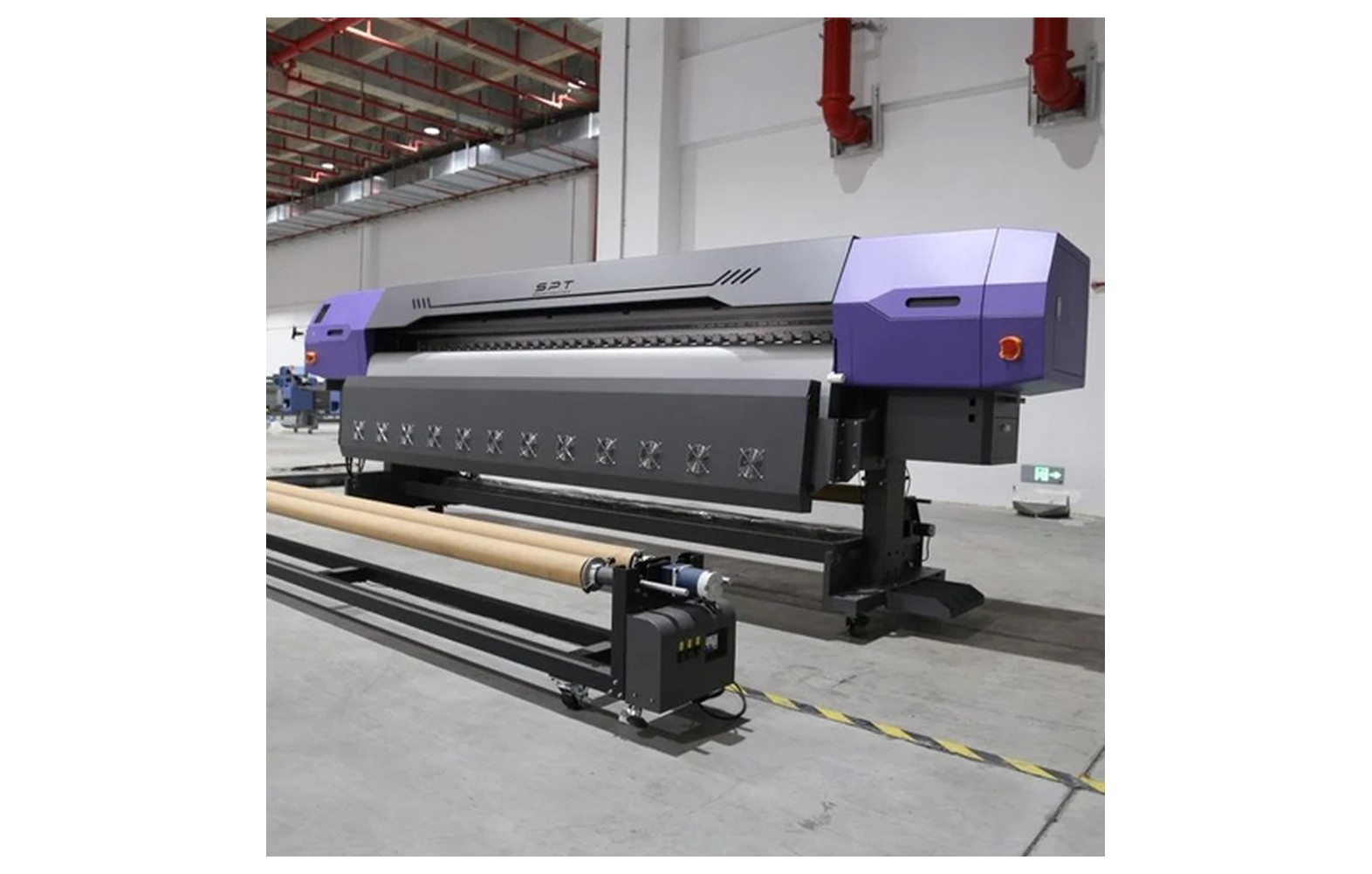
Direct answer: In a scanning inkjet printer, a carriage supports the printheads and moves across the print area. Rails guide its motion, while the drive and position-feedback system help the controller coordinate position and firing. Component design varies by machine.
Engineering Principles and Components
| Topic | Function | Practical check |
|---|---|---|
| Carriage | Carries the printhead assembly across the printing area. | Check permitted clearance and look for reported motion errors. |
| Guide rails | Guide carriage travel. | Use the manufacturer service schedule and approved lubrication. |
| Drive system | Moves the carriage using the machine-specific motor and transmission. | Do not adjust tension or replace parts without the service procedure. |
| Encoder or position sensor | Provides position information to the controller on systems that use it. | Contamination or damage can affect feedback; cleaning is model-specific. |
Practical Shop Checklist
- Identify the printer model and its motion system before diagnosing.
- Record whether the fault appears at a consistent position or across the entire scan.
- Use the authorised inspection and isolation procedure; moving parts can cause injury.
- Escalate carriage strikes, damaged encoders or electrical faults to qualified service.
Why Carriage Motion Matters
In a scanning inkjet printer, the carriage carries the printhead assembly across the print area. During a scan, the controller coordinates nozzle firing with carriage position. The substrate or bed then moves according to the machine’s design, allowing the image to be built over successive scans. Accurate printing depends on the movement system, position feedback, jetting and media handling working together.
The carriage is not simply a platform sliding from one side to the other. It can carry printheads, ink connections, electrical cables and sensors. Guide rails constrain its travel, a drive mechanism provides movement and a feedback system helps the controller determine position. The exact arrangement varies between machines. Some printers use stationary lineheads rather than a scanning carriage.
This guide explains the functions and a safe diagnostic approach. It is not a service manual. Moving parts, electricity, chemicals and UV components can be hazardous. Do not open guards, move the carriage by hand or adjust belts and sensors unless the manufacturer authorises the procedure for your role and machine.
The Motion System at a Glance
| Component | Typical function | Why it matters |
|---|---|---|
| Carriage | Supports and moves the head assembly in a scanning printer | Helps position nozzles relative to the substrate. |
| Guide rail or guide mechanism | Constrains carriage travel | Supports consistent motion along the designed path. |
| Drive motor and transmission | Provide controlled carriage movement | Speed and positioning must follow controller commands. |
| Encoder and sensor | Provide position feedback in designs that use them | Help coordinate firing with carriage position. |
| Controller | Coordinates commands, feedback and firing | Connects the motion system to the processed print data. |
| Media or bed movement | Positions the material between scans | Affects where successive parts of the image are placed. |
This is a functional overview, not a universal parts list. A machine may use a different drive or feedback arrangement. Consult its documentation before identifying a component or choosing a maintenance procedure.
How the Carriage Builds an Image
The RIP prepares the artwork and sends print data to the printer. During a scan, selected nozzles fire as the carriage moves. The controller uses the machine’s timing and position information to determine when to place droplets. After a scan, the printer may advance the roll or reposition the bed before printing another portion of the image.
The number of scans used to build a section is often described through a pass mode, though definitions differ between manufacturers. A mode can also specify direction, resolution and other settings. More passes may change the appearance of some defects and the time required, but they do not repair a mechanical fault or missing nozzles.
Some printers fire in both directions of travel, while others use a unidirectional option or a different architecture. Bidirectional printing relies on appropriate timing and alignment for the selected configuration. The correct test and adjustment are specific to the machine, head height, media and mode.
What the Carriage Carries
A carriage assembly may include one or more heads, associated wiring, ink connections and sensors. Some UV printers also have curing components associated with the moving assembly, depending on the design. The arrangement is determined by the manufacturer and should not be inferred from another model’s photographs.
The assembly must move through its intended path without contacting the substrate, fixtures or other obstructions. A head strike can damage the head or affect alignment and other parts. If a strike occurs, stop safely and follow the manufacturer’s instructions. Do not continue production merely because the machine still moves.
Before a job, check material and fixtures using the approved loading and height procedure. Raised corners, wrinkles, loose objects or an unsuitable fixture can present a hazard. The highest point in the travel path matters. Do not use a universal head-height number for every printer or material.
Guide Rails and Controlled Travel
Guide rails or other guiding mechanisms constrain the carriage along its designed path. Their construction may involve bearings, wheels or linear guides depending on the printer. Proper alignment, condition and maintenance support predictable movement, but the details are specific to the equipment.
Dust, ink mist, wear, an obstruction or incorrect maintenance can potentially affect mechanical motion. Unusual noise or resistance deserves attention, but it does not automatically prove that a rail needs replacement or lubrication. A technician should diagnose the system using the manufacturer procedure.
Use only the approved maintenance method, material and interval. An unapproved lubricant can attract contamination or affect adjacent components, and some surfaces may require a different treatment. Do not apply oil or grease based on a generic online recommendation. If the user manual does not authorise a task, ask service.
Motor, Belt and Drive Mechanism
The carriage is moved by a machine-specific drive arrangement. It may use a motor and belt, another transmission or a different mechanism. The controller commands movement and uses the available feedback to manage the path and timing. The appropriate service adjustments depend on the design.
A loose or damaged drive component is one possible cause of motion trouble, but similar symptoms can result from an obstruction, sensor problem, control fault or other issue. An operator should note unusual sounds, errors and when the fault appears instead of changing belt tension by guesswork.
Do not reach into a moving machine or adjust a belt while the equipment is operating. Electrical isolation, stored energy and safe access requirements are model and site specific. Belt replacement, tensioning and motor diagnosis should be handled by personnel trained and authorised for the equipment.
What Is an Encoder Strip?
In printers that use one, an encoder strip is a marked strip read by a sensor as the carriage moves. The controller uses this feedback as part of its position and motion control. Other machines use different sensors or feedback systems, so the presence, location and function of a strip should be confirmed in the manual.
If an encoder or its sensor is contaminated, damaged or not correctly read, the printer may experience positioning problems or report an error. That is a possible cause, not a conclusion from a blurry print. A nozzle fault, alignment setting, media issue or mechanical problem can produce overlapping symptoms.
Encoder surfaces can be delicate. Do not scrape, bend, disconnect or clean a strip with an unapproved fluid. Some manufacturers provide a user-level cleaning procedure, while others reserve the work for service. Follow the procedure for the exact machine, including any required isolation and access steps.
Position Feedback and Droplet Timing
A moving head ejects droplets that travel a short distance before landing on the substrate. The controller must account for motion and timing so the resulting marks land in the intended positions. The actual calculations and controls are specific to the head, machine and print mode.
When printing in opposite carriage directions, timing or alignment errors can make edges or vertical lines appear doubled or offset. The symptom can also have other causes. A model-specific alignment pattern helps assess the adjustment; a nozzle check should be considered first where the manufacturer recommends it.
Head-to-media gap matters because it changes the droplet’s travel distance. The permitted gap is design specific. Too little clearance risks contact with the media or fixture, while an excessive gap can reduce placement accuracy in some systems. Follow the machine’s height procedure and use the actual production material.
Carriage Alignment Versus Media Feed Calibration
Carriage or printhead alignment concerns the placement of printed marks relative to the machine’s motion and, where relevant, other heads or scan directions. Media-feed calibration concerns how the substrate advances between print operations. Print-and-cut registration, where supported, concerns the relationship between printed artwork and a cutter’s path.
These adjustments are related in a finished job but are not interchangeable. Altering the feed setting does not automatically correct bidirectional head alignment, and an alignment test does not repair missing nozzles. Use the correct manufacturer pattern and record the original values before an authorised change.
When comparing tests, keep the media, ink, mode and other conditions consistent. Follow the sequence in the printer manual because some manufacturers specify checking nozzles or media settings before alignment. Do not apply a correction value found for a different model.
Common Symptoms and Possible Causes
| Observation | Possible areas to investigate | Safe starting point |
|---|---|---|
| Vertical lines appear doubled | Bidirectional alignment, motion, jetting or print mode | Save a nozzle check and use the manufacturer alignment procedure. |
| Carriage error at a particular position | Obstruction, sensor, drive or other model-specific fault | Stop safely and record the exact error and location. |
| Unusual movement noise | Mechanical contact, drive or guide condition | Stop and request inspection; do not lubricate by guesswork. |
| Horizontal banding | Nozzles, feed, alignment, ink delivery or mode | Keep samples and start with the documented diagnostic sequence. |
| Fault after contact with media | Possible head, carriage or alignment damage | Stop safely and request qualified inspection. |
| Artwork offset on the substrate | Loading, origin, RIP placement or registration | Check the job and model-specific positioning procedure. |
A symptom can have more than one cause. The table does not replace the manufacturer’s fault-code instructions. Avoid changing several controls or replacing a sensor before preserving the original evidence.
A Safe Troubleshooting Sequence
- Stop if there is a hazard. A strike, loose fixture, leak, electrical warning or unusual mechanical contact requires a safe stop and the manufacturer’s escalation procedure.
- Describe the defect. Record the exact error, the affected print area, direction and job. Note whether the issue appears at a repeatable position or across the full width.
- Review recent changes. List the media, head height, mode, maintenance or configuration changes made before the symptom appeared. Timing is useful evidence but does not prove causation.
- Keep a baseline. If the machine is safe to operate, print and label the approved nozzle check and any manufacturer-directed test. Retain the original output.
- Check operator-accessible conditions. Review loading, visible clearances and the control-panel status as allowed by the manual. Do not enter guarded areas or move the carriage manually.
- Use the correct authorised test. If the manual directs an alignment or feed check, use the specified media and mode. Record the original setting and make one approved change at a time.
- Compare and escalate. Keep the new pattern and note the result. If the fault persists, recurs or requires mechanical or electrical access, involve an authorised technician.
The manufacturer may specify a different sequence for a particular printer. Follow its instructions and the site’s safety rules. A documented history helps the engineer understand the issue without unnecessary repeated adjustments.
Example: Double Vertical Edges
A shop sees a fine vertical line that appears doubled on a roll print. The operator keeps the affected sample, records the print mode and checks the printer’s approved nozzle pattern. If the manual directs an alignment check after confirming jetting, the operator prints the correct test on suitable media.
The operator follows only the user-level adjustment procedure, recording the original and new values. They then print the same sample again. If the symptom remains or the printer reports a fault, they stop and share the samples with service. This illustrative sequence does not prove that every doubled edge is caused by bidirectional alignment.
Example: A Carriage Strike on a Flatbed
During a job, a raised item or fixture contacts the moving assembly. The operator stops the printer safely, preserves the job details and follows the manufacturer’s incident procedure. They record the material, fixture, height setting and any error message without attempting to realign or dismantle the head.
A qualified technician can assess whether the head, carriage, guide system or alignment was affected. Before production resumes, the shop checks the approved hold-down and clearance procedure and validates a sample. A clear-looking head surface alone does not establish that the assembly is undamaged.
Routine Care Without Guesswork
Use the equipment’s maintenance schedule for the carriage and guide system. The schedule may identify specific user-accessible checks and service-only tasks. Keep the print area free from obstructions using the authorised method and maintain the workshop conditions specified by the manufacturer.
Do not use compressed air, solvents or lubricants on sensitive components unless the manual explicitly permits them. Cleaning materials and methods that work for a different model may damage an encoder, bearings or nearby ink components. Ask the service provider for the correct consumables and training.
Record dated nozzle tests, errors, service visits and repairs. Note any recurring sound or symptom and the conditions under which it occurs. A service log should not contain passwords or unnecessary customer artwork. Include the part and service documentation when a qualified technician replaces a component.
Questions to Ask a Service Engineer
- Which motion and position-feedback components are installed on this exact printer?
- What evidence distinguishes the suspected fault from a nozzle, feed or alignment issue?
- Which checks are safe for the operator and which require isolation and service access?
- Is there an approved encoder-cleaning procedure, and who is authorised to perform it?
- What maintenance materials and intervals are specified for the guide system?
- What test will confirm acceptable operation after the repair?
- What parts, labour and warranty terms apply to the proposed work?
Request a written service report and keep the before-and-after tests. If an adjustment is made, record the setting or procedure as appropriate under the manufacturer’s instructions. The goal is a repeatable, safe result, not simply clearing an error message.
Related Guides
Read our digital printer anatomy guide, printhead alignment guide and media feed calibration guide. For each procedure, follow the documentation for the installed printer and the actual substrate.
Related Engineering Guides
Start with how a piezo printhead works and digital inkjet machine anatomy. For a machine-specific question, share your model on our contact page.
Frequently Asked Questions
Does every printer use a moving carriage?
No. Scanning printers use carriage motion, while some linehead systems keep heads stationary and move the substrate.
What is an encoder strip?
In compatible designs it is a marked strip read by a sensor to provide position information. Not every machine uses the same arrangement.
Can a dirty encoder cause alignment problems?
It can affect position feedback in applicable designs, but other causes are possible. Follow the manufacturer diagnostics.
Can I lubricate the rail with any oil?
No. Use only the product and procedure specified for the machine.
What causes a carriage strike?
Possible causes include raised or warped media, incorrect clearance and motion faults. Stop the job and inspect under the approved procedure.
Should I adjust the drive belt myself?
Only if authorised and trained under the manufacturer instructions; incorrect adjustment can create damage or safety risks.
How do I distinguish a head fault from a motion fault?
Record the pattern, run approved nozzle and calibration tests and have a technician interpret the results.
