



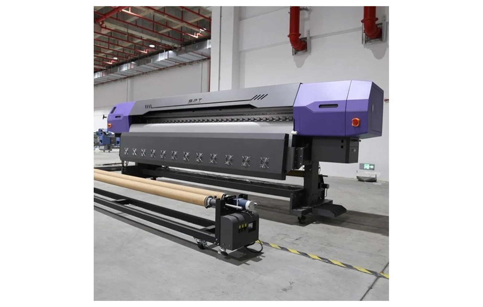
Direct answer: A vacuum table uses a pressure difference to help hold suitable flat media on a flatbed during printing. Bed design, zones, airflow and permitted materials vary by machine. A vacuum is not a substitute for checking the substrate, clearance and manufacturer instructions.
Engineering Principles and Components
| Topic | Function | Practical check |
|---|---|---|
| Bed and surface | Supports the substrate in the print area. | Keep the surface clean and inspect it as instructed. |
| Vacuum source | Creates the pressure difference used for hold-down. | The source and maintenance requirements are model-specific. |
| Zones and valves | Some beds let operators select areas. | Check whether unused zones should be closed or covered under the manual. |
| Substrate | The media must lie suitably flat and cover the relevant area. | Porosity, rigidity and surface condition affect hold-down. |
Practical Shop Checklist
- Confirm that the machine is designed for the substrate and object dimensions.
- Follow the supplier procedure for selecting or covering zones.
- Check hold-down and printhead clearance before starting.
- Do not assume a vacuum bed can safely hold warped, porous or irregular material.
What a Vacuum Table Does
A vacuum table is a hold-down system used on some flatbed printers. It creates a pressure difference between the air above a suitable substrate and the air beneath it. The surrounding air presses the material towards the bed, helping it remain flat and in position while the printer operates.
The system is not a universal clamp. Its effectiveness depends on the bed design, the area and condition of the substrate, its porosity and stiffness, the selected zones, leaks and the vacuum source. An item that looks flat at one point may lift elsewhere. An operator must still follow the machine’s loading, clearance and hold-down instructions.
Not every flatbed has the same bed surface, zone arrangement, pump or control method. Some machines use fixtures or other hold-down systems. This guide explains the principles and safe operator checks; the installed equipment’s manual governs settings, service and safety.
The Engineering Principle: Pressure Difference
The vacuum source lowers pressure in a designed space or air path beneath the substrate. The pressure above the material is then greater than the pressure beneath it. That difference produces a force towards the bed over the area where the pressure difference is effective.
As a simplified relationship, force is the pressure difference multiplied by effective area. This is not a practical guarantee that a particular item is safely held. Real beds have airflow, leaks, zones, uneven surfaces and material behaviour that affect the available pressure difference and contact. The printer manufacturer must define the permitted setup.
A large flat non-porous sheet may behave differently from a small porous or warped item on the same bed. A small item has less area available for hold-down, while a porous material may allow substantial airflow through it. Rigidity and curl can oppose the intended contact. Test the actual material using the approved procedure.
Main Components of a Vacuum Bed
Bed surface: The surface supports the substrate and contains or connects to the manufacturer’s designed air path. It may include holes, channels or another configuration. Keep it clean using the specified method; do not block or alter openings without approval.
Vacuum source: A pump, blower or other device creates the intended pressure and airflow for the system. Different source types behave differently. A loud sound or a running motor alone does not prove that the correct hold-down is available at the bed.
Zones and controls: Some beds divide the surface into selectable regions. Valves or software may control them. Other beds use a different arrangement. The number of zones and the correct setup depend on the printer.
Air paths and seals: Hoses, channels, fittings and seals connect the bed and vacuum source in some designs. Their arrangement is machine specific. Leakage, obstruction or damage can affect performance, but internal diagnosis and repair should follow the service manual.
Zones: Selecting the Area Being Used
Zone control can help direct the system’s hold-down capability to the part of the bed carrying the job. If a machine has selectable zones, follow its instructions for the actual material size and placement. Not every printer has zones, and the controls are not necessarily comparable between models.
Unused open areas may influence airflow in some systems. The manufacturer may specify closing zones or covering certain exposed areas, but covering methods, materials and limits vary. Do not block openings, cover a bed or restrict airflow based on a generic online recommendation. An unapproved arrangement can affect performance or equipment operation.
Record the zone selection with the job setup. If hold-down is weak in a specific area, note the location and compare it with the manual. Avoid concluding that a pump or valve has failed without the relevant tests.
Substrate Area, Porosity and Stiffness
Area: The effective contact area influences the available hold-down force in the simplified pressure model. A small piece may be harder to hold than a large sheet, but the result depends on the complete bed and fixture design.
Porosity: Porous materials can allow air to move through the substrate, potentially reducing the pressure difference across it. Wood, textiles and other materials vary widely, including with coatings. Do not assume that a material is either suitable or unsuitable based only on its generic name.
Stiffness and flatness: A rigid board can bridge a low area or resist being pulled flat if it is warped. A flexible sheet may conform more readily but can wrinkle or lift at an edge. The safe decision is based on the actual item and the manufacturer’s procedure, not the nominal sheet thickness alone.
Surface and contact: Dirt, damage, coatings or uneven features can affect how the material contacts the bed. Clean and inspect only as authorised. If an item cannot be held securely, ask the supplier about an approved fixture or alternative process.
Vacuum Hold-Down and Head Clearance
A vacuum bed helps hold suitable media but does not eliminate the risk of a head strike. A lifted corner, warped board, raised feature or loose jig can reduce the distance between the item and the moving head. The highest point in the complete carriage path matters.
Use the printer’s specified height measurement or sensor procedure. A sensor may have limitations for particular shapes or materials, so follow the manual and do not bypass it. Check the actual substrate and any fixture. If the material moves or lifts, stop safely before the carriage contacts it.
Do not increase the head height beyond approved limits or add unapproved weights and clamps to keep a job running. An improvised solution can create a new obstruction or change print quality. Seek a manufacturer-approved arrangement.
Vacuum Source: Pressure and Airflow Are Different
Pressure difference describes the difference between two pressures. Airflow describes how much air moves through the system over time. Both can matter to a vacuum-table design. A source that handles an open, porous setup may have different characteristics from one designed for a more sealed arrangement.
Published numbers must be interpreted in the context of the complete machine, bed, zones and substrate. A pump rating alone does not tell you whether a particular item will be held safely. Ask the printer supplier for supported materials and setup guidance instead of comparing a single specification in isolation.
Do not alter a pump, valve, regulator or hose arrangement to increase hold-down without the manufacturer’s approval. Incorrect modifications can affect equipment operation or safety. Electrical, mechanical and internal fluid or air-path work should be performed by qualified service personnel.
Vacuum Versus Fixtures and Jigs
Vacuum is one possible method of holding suitable flat material. Irregular objects may require a manufacturer-approved jig or fixture, depending on the printer and application. A fixture must locate the item securely, remain stable during the scan and fit within the machine’s height and travel limits.
Vacuum and fixtures can be used together only where the manufacturer permits the arrangement. A jig that blocks the intended airflow, raises the object or shifts under movement can introduce new risks. Do not assume an object is safe because it rests in a recess.
For repeat jobs, document the approved fixture, orientation, height procedure, zone settings and print origin. Keep a physical proof. If the object or fixture changes, reassess the setup instead of reusing a previous setting without checks.
Step-by-Step Setup for a Suitable Sheet
- Confirm the job. Check that the printer supports the material, dimensions, weight and intended application. Review the supplier’s handling instructions.
- Inspect the bed. Use the authorised procedure to check for contamination, damage or obstructions. Do not clean internal parts or open guards unless permitted.
- Inspect the substrate. Look for warp, curl, uneven surfaces, damage and raised features. Consider the entire carriage path.
- Place the material. Load it in the orientation and position specified for the machine. Keep hands clear of moving parts.
- Select the approved zones. Use only the manufacturer’s permitted zone or covering arrangement for the job.
- Check hold-down. Use the specified operator procedure to confirm that the sheet is secure. Do not move it while the carriage or bed is operating.
- Check height and clearance. Follow the exact measurement or sensor method, including the highest point and any fixture.
- Print and inspect a proof. Use the documented ink, RIP and curing workflow. Confirm appearance and any agreed end-use tests.
- Monitor and record. Follow the manufacturer’s supervision instructions. Stop safely if material lifts or shifts, and retain the approved setup for repeat work.
Common Hold-Down Problems
| Observation | Possible factors | Safe first action |
|---|---|---|
| One corner lifts | Warp, contamination, zone setup or local leakage | Stop and inspect the material and approved setup. |
| A small item moves | Limited area, item shape or an unsuitable fixture | Ask about a manufacturer-approved fixture or alternative process. |
| Hold-down is weak across the bed | Zone selection, material, airflow or equipment fault | Check operator controls and contact service if unresolved. |
| Porous material will not remain flat | Airflow through the material or insufficient contact | Confirm suitability and the approved hold-down method. |
| Unusual sound or electrical warning | Vacuum source or another equipment fault | Stop safely and request qualified inspection. |
| Material lifts during a job | Loading, substrate behaviour or system condition | Stop before contact and follow the incident procedure. |
The table identifies possible areas, not a diagnosis. Similar symptoms can arise from several causes. Keep the affected material and record the selected zones, location and any warning for the service provider.
Troubleshooting One Variable at a Time
Start by describing exactly where and when the material moves. Record its size, thickness, supplier, batch and condition, along with the zone selection and fixture. If the same machine holds a different approved material, note the comparison, but do not treat it as proof that the first material is unsuitable.
Follow the manual’s operator-level checks for loading, visible bed condition and controls. Use only approved changes to zone or covering arrangements. If a change is made, record it and repeat the same safe check. Do not reach into the machine while the bed, carriage or other parts are moving.
If the issue remains, stop and ask the supplier or technician to assess the bed, air paths and vacuum source under the service procedure. Do not disconnect hoses, bypass a valve or change pump wiring as a trial. A model-specific test is needed to distinguish a material limitation from an equipment fault.
Example: A Warped Sign Board
A shop loads a rigid board for UV printing and notices that one corner remains raised after the approved hold-down sequence. The operator stops the setup, records the material and checks the bed and zone settings using the manual. The raised corner is also included in the height assessment.
If the board cannot be held within the manufacturer’s requirements, the shop uses an acceptable replacement or asks the supplier about an approved fixture. They do not place an unapproved weight in the carriage path. This example does not imply that vacuum can flatten every warped board.
Example: A Small Promotional Item
A customer requests UV printing on a small item that does not cover much of the bed. The operator checks whether the machine and ink support the item and asks about an approved jig. The fixture must hold the item securely and fit within the height and travel limits.
The team records the item’s orientation, print origin, fixture and approved settings, then produces a physical proof. Adhesion and intended-use suitability are tested separately as agreed. This is an illustrative workflow, not a claim that any particular promotional item is compatible.
Example: Uneven Hold-Down in One Zone
An operator finds that a suitable sheet lifts in one area while another area appears secure. They stop the job and record the sheet condition, position and zone selection. They check the normal operator controls and bed surface using the manual’s permitted procedure.
If the fault persists, they provide the evidence to service. A zone valve, air path, seal, material or another factor may be relevant, but the operator does not open the system or replace a pump based on the symptom alone.
UV Print Quality Is More Than Hold-Down
Secure loading helps maintain position and clearance, but it does not establish colour accuracy, cure, adhesion or durability. The ink, substrate, surface preparation, RIP settings, lamp system and intended use all matter. A dry-feeling surface alone does not prove complete UV cure.
Agree test methods and acceptance criteria with the ink, printer and substrate suppliers and the customer. Do not claim food-contact, dishwasher or outdoor suitability without evidence for the complete application. Use a qualified laboratory when the application requires independent testing.
Keep UV guards and interlocks in place and follow the ink safety data sheet. Lamp, electrical and internal mechanical service belongs to trained personnel. For spills, faults or exposure incidents, follow the site’s safety and escalation procedure.
Maintenance and Service Records
Use the manufacturer’s schedule for bed cleaning, vacuum-system service and consumables. Clean only with approved materials and methods. A substance that damages the bed surface or blocks an air path can create additional problems. Do not use generic solvents or compressed air unless explicitly permitted.
Record recurring weak areas, alarms, service visits and authorised repairs. Retain the material and job information where useful. Ask the technician what evidence supports the diagnosis, which parts are approved and what test verifies operation after repair.
Vacuum sources may involve moving parts and electrical energy. Do not open enclosures, modify wiring or bypass safety devices. Stop safely for unusual noise, odour or warnings and use qualified service support.
Questions to Ask the Printer Supplier
- Which substrates, dimensions and item weights are approved for this bed?
- Does the bed have selectable zones, and how should they be used for small sheets?
- Are coverings or fixtures permitted, and which designs are approved?
- How should an operator verify hold-down and head clearance?
- What are the limitations for porous, warped or irregular material?
- Which bed-cleaning and maintenance procedures are user accessible?
- What symptoms require service, and what post-repair test is recommended?
- What UV ink, curing and end-use documentation applies to the intended job?
Keep the answers alongside the printer manual and job setup record. A documented proof and safe loading method help a shop repeat work more consistently than an unsupported claim that vacuum will hold every material.
Related Guides
Continue with vacuum hold-down troubleshooting, head clearance and strike prevention and UV cure and adhesion testing. Always use the instructions for your own printer and material.
Related Engineering Guides
Start with how a piezo printhead works and digital inkjet machine anatomy. For a machine-specific question, share your model on our contact page.
Frequently Asked Questions
What does a vacuum table do?
It helps hold suitable material flat through a pressure difference during printing.
Do all UV flatbeds have vacuum beds?
No. Features vary by model; ask the supplier about the actual bed and fixtures.
Why might media not hold properly?
Possible causes include unsuitable material, open zones, leaks, contamination or a vacuum-system issue. Follow the manual.
Can a vacuum bed hold any object?
No. Irregular, porous, heavy or warped items may need a manufacturer-approved fixture or another method.
Should I cover unused holes?
Only as directed by the printer manufacturer; beds and zone systems differ.
Does the vacuum replace a clearance check?
No. Inspect the material and highest point before starting the print.
How should a vacuum table be maintained?
Use the manufacturer’s maintenance and safety instructions for the bed and vacuum source.
