



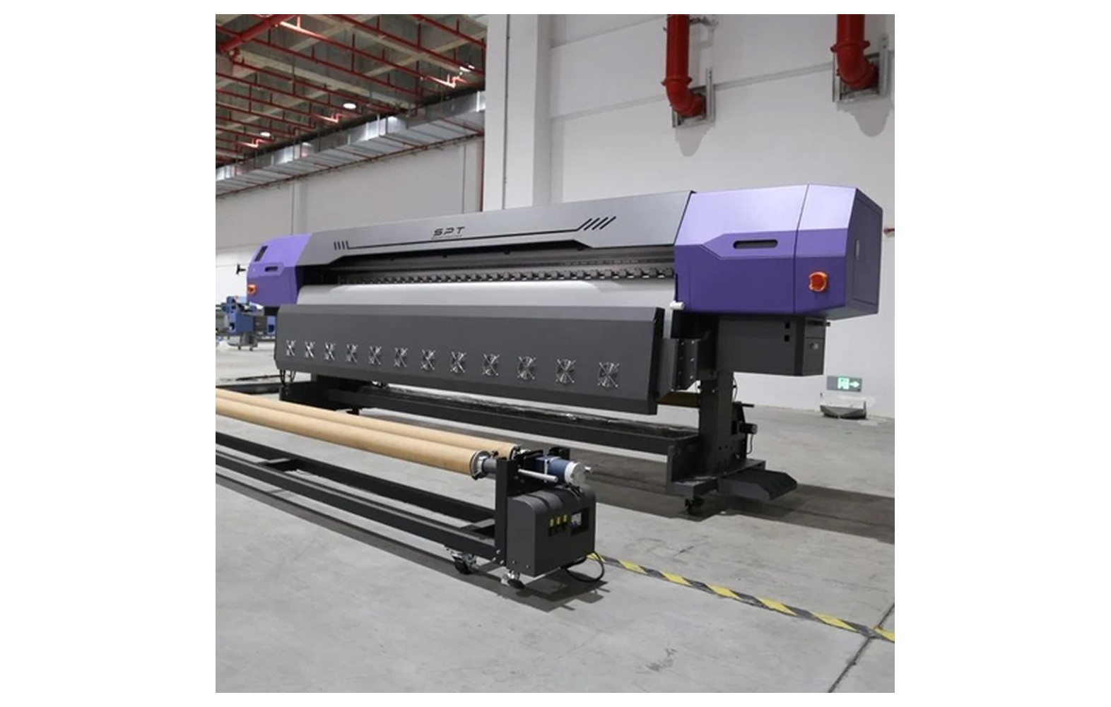
Direct answer: Printhead clearance is the distance between the head and the substrate in a particular machine. Too little clearance can allow raised media or an incorrectly loaded object to contact the head; the acceptable range and adjustment method are model-specific.
Engineering Principles and Components
| Topic | Function | Practical check |
|---|---|---|
| Media flatness | Raised or warped material can reduce clearance. | Use supported media and inspect the complete travel path. |
| Object thickness | Flatbed items may vary in height or have raised features. | Measure the highest point and check the manufacturer limit. |
| Approved height setting | The printer may offer specific height settings or sensors. | Do not exceed or bypass manufacturer limits. |
| Head strike response | Contact can damage the head or affect alignment. | Stop safely and follow the incident and service procedure. |
Practical Shop Checklist
- Inspect substrates, fixtures and edges before printing.
- Verify the highest point and available clearance under the manufacturer method.
- Never bypass collision sensors or guards.
- Record the event and seek service if impact or damage is suspected.
What Is Printhead Clearance?
Printhead clearance is the space between the printhead assembly and the surface being printed, as defined and controlled by the particular machine. In a scanning inkjet printer, the head moves across the print area while droplets travel to the substrate. The correct clearance depends on the head, printer, material, fixture and selected print mode.
Too little clearance can allow a raised edge, wrinkle, seam or incorrectly positioned item to contact the head or another part of the carriage. Too much clearance can make droplet placement less accurate in some systems. There is no universal safe gap that can be applied to all UV, DTF, textile or roll-to-roll printers.
Use the manufacturer’s height-setting and loading procedure for the actual machine. Check the complete travel path, not just the point directly beneath the head at the start of a job. Guards and collision sensors are protective measures, not permission to load an unstable item or bypass the specified checks.
What Is a Head Strike?
A head strike is contact between the printhead or moving assembly and material, a fixture or another obstruction. A curled sheet, lifted film edge, thick seam, misplaced jig or loose object can create a contact risk. The exact part that makes contact depends on the machine and the incident.
A strike can damage the nozzle plate, disturb alignment, affect a carriage component or create another fault. The extent cannot be established just by seeing that the printer still moves. If contact occurs, stop safely and follow the manufacturer incident procedure. Preserve the job details and request qualified inspection when required.
Do not continue printing simply to see whether the fault goes away. Do not manually force the carriage away from an obstruction or reach into a moving machine. Follow the site’s safe-stop and isolation instructions and leave restricted service to trained personnel.
Why the Highest Point Matters
On a flatbed, an item may not be uniformly thick. Raised lettering, curved edges, a handle, a fastener or a fixture can be higher than the main printable surface. On a roll printer, a wrinkle or lifted edge may become the highest point in the path. Measuring only the nominal sheet thickness can therefore be misleading.
Use the measurement or sensor method prescribed by the manufacturer. Confirm how the machine defines object thickness and clearance, and check the complete region the carriage will travel across. A sensor can assist the documented workflow, but it may have limitations for certain shapes, reflectivity or materials. Ask the supplier about the actual device and do not bypass it.
If the item cannot be supported securely within the specified limits, do not improvise a fixture or modify the height system. Ask the manufacturer whether an approved jig, alternative process or different machine is appropriate.
How the Gap Affects Droplet Placement
After a nozzle ejects a droplet, the drop travels through the gap before reaching the substrate. The printer synchronises firing with head and media movement. A change in the gap can affect the way placement errors appear, particularly in fine text, bidirectional output or multi-layer registration.
Different heads have different designs and operating ranges. Some systems are specifically designed for a larger gap than others. A larger gap is not automatically unacceptable, and a smaller gap is not automatically better if it creates a collision risk. Follow the exact equipment specification and verify a representative sample.
Head alignment may be affected by the installed configuration and selected media height. If the manual requires an alignment check after a height or media change, use the specified pattern and material. Do not copy an alignment value from another machine.
Roll-to-Roll Risks: Wrinkles and Raised Edges
Flexible media can curl, wrinkle, shift or lift as it travels through a printer. Possible factors include loading, roll condition, material properties, roller placement, tension, the platen system and the environment. These factors interact, so a lifted edge does not automatically identify a single faulty part.
Before printing, inspect the roll for damage, creased edges and uneven winding. Load the material through the path and guides specified for the printer. Confirm that the roll width, weight and core are supported. Use the manufacturer’s approved settings for the actual media.
During a run, stop safely if the web becomes wrinkled or rises towards the carriage. Do not push it flat while rollers are moving. Follow the documented reloading and troubleshooting sequence. If the condition persists, contact the supplier rather than increasing head height beyond the approved configuration.
Flatbed Risks: Warped Boards and Loose Fixtures
A flatbed can carry sheets, objects or fixtures with different shapes. A warped board may sit flat at the point measured but lift elsewhere. A loose jig can move under carriage travel or handling. Some beds use vacuum zones, but vacuum does not guarantee that every porous, curved or irregular item will remain secure.
Use the manufacturer’s approved hold-down method and confirm the material is suitable for the bed. Where a jig is required, ensure it is approved for the item, secured correctly and included in the height check. Do not cover vacuum zones or add weights in an improvised way unless the manufacturer authorises that arrangement.
Check the object and fixture across the complete travel path. If the substrate moves or the bed cannot hold it within the required clearance, stop and seek an approved solution. Never treat an automatic height sensor as a substitute for secure loading.
Textile Risks: Seams, Lint and Uneven Surfaces
Garments and other textiles may have seams, folds, pockets, zips or raised fibres. A surface that appears flat from a distance can have a local high point in the head path. The appropriate platen, fixture and preparation depend on the printer and textile process.
Use the equipment’s specified loading and securing method. Check for folds and protrusions before starting the scan, and follow the approved height procedure. Do not flatten a garment by placing hands in the moving area or attaching unapproved objects to the platen.
Lint and contamination may also affect print quality or maintenance. Follow the printer and material suppliers’ instructions for preparation and cleaning. A poor nozzle check after a textile job does not by itself prove a strike; use the documented diagnostic sequence.
Head Height and Print Quality
A clearance problem may affect more than the risk of contact. Depending on the machine and job, incorrect height or related alignment can contribute to fuzzy edges, fine-line displacement, overspray or registration differences. These symptoms can also arise from nozzles, artwork, media or print settings.
When evaluating a height change, use only supported settings and keep other factors constant. Print a representative sample with fine text, edges and any relevant white layers. Record the material, fixture, height setting and mode. If the result is not acceptable within the approved operating range, seek supplier guidance rather than exceeding limits.
For bidirectional printing, the manufacturer may provide a specific alignment pattern for the configuration. Confirm nozzle condition first if required by the manual. Alignment is not a repair for damaged nozzles or unstable substrate handling.
Height Sensors and Collision Detection
Some printers use sensors to detect media height or potential obstructions. The sensor’s field of view, sensing method, response and limitations are specific to the machine. It may not reliably identify every transparent, reflective, narrow or irregular feature in every configuration.
Consult the manual to understand what the sensor checks and what remains the operator’s responsibility. Keep protective systems enabled and use the approved checks. Do not tape over a sensor, bypass an interlock or alter a safety setting to complete a job.
If a sensor reports an error, stop and follow the manufacturer’s troubleshooting instructions. The cause could involve the item, loading, sensor condition or another fault. Internal testing or adjustment should be performed by qualified service personnel.
Safe Pre-Print Checklist
- Identify the job. Confirm the actual substrate, object, fixture and intended print area. Check that the equipment supports the material and dimensions.
- Inspect the material. Look for warping, curls, wrinkles, seams, raised features or loose parts that could enter the carriage path.
- Secure the item. Use the manufacturer’s approved loading, vacuum or fixture procedure. Verify that the material cannot shift during the job.
- Check the highest point. Follow the specified measurement or sensor method for the full area and fixture. Do not rely only on nominal thickness.
- Select the approved configuration. Use the supported height, media and RIP settings for the exact machine and job.
- Confirm normal operation. Perform the manufacturer-required nozzle and alignment checks where appropriate. Do not operate with unresolved safety or motion warnings.
- Print a representative proof. Inspect the item and output under agreed conditions. Continue only if the material remains secure and the result is acceptable.
- Monitor as instructed. Stop safely if material lifts, shifts or creates an unexpected obstruction.
What to Do After a Suspected Strike
Stop safely. Use the equipment and site procedure. If there is an electrical fault, ink leak, damaged guard or other hazard, follow the relevant emergency and isolation instructions. Do not reach into moving equipment.
Preserve the evidence. Record the job, material, fixture, height setting, time, any warning and where contact appeared to occur. Take photographs only when safe and permitted. Keep the affected print and relevant test patterns.
Do not improvise a repair. Do not scrape the nozzle plate, force the carriage, adjust internal parts or run repeated cleaning cycles in the hope that the problem resolves. Follow the manufacturer’s incident procedure and contact qualified service.
Validate before returning to production. The technician may need to inspect the head, carriage, sensors and alignment according to the machine’s service documentation. Ask which checks demonstrate that the printer is ready and retain the service report. Correct the loading or fixture issue before restarting the job.
Symptoms After Contact: What They Do and Do Not Prove
| Observation | Possible concern | Responsible response |
|---|---|---|
| New gaps in a nozzle check | Jetting may have changed, but the cause needs assessment. | Save the pattern and follow service guidance. |
| Blurred or doubled lines | Placement or alignment may have changed. | Do not adjust restricted mechanisms; request the correct diagnostic sequence. |
| Carriage error or unusual noise | A mechanical or sensor fault may be present. | Stop safely and contact qualified service. |
| No visible defect on a quick print | Damage is not ruled out by appearance alone. | Follow the manufacturer’s post-incident inspection procedure. |
| Material remains lifted | The original collision risk persists. | Do not restart until an approved loading solution is in place. |
Example: A Warped Rigid Sheet
A shop loads a rigid board that has a slightly raised corner. The operator checks the item using the manufacturer’s method and notices that the corner could enter the carriage path. The shop stops setup and consults the approved hold-down procedure instead of assuming the nominal board thickness is sufficient.
If the material cannot be held flat and secure within the equipment’s requirements, the shop requests another sheet or an approved fixture. A proof is made only after the loading condition is resolved. This example does not imply that every warped board can be corrected by vacuum.
Example: Curling Roll Media
A roll-to-roll job develops a curl near an edge. The operator stops safely before the raised material can contact the head, records the media and settings and checks the loading path under the manual. The team reviews the roll condition, guides, roller placement and take-up setup where applicable.
If reloading under the approved procedure does not resolve the issue, the shop contacts the supplier. Raising the head beyond its approved setting or holding the edge down by hand during operation is not an acceptable substitute for diagnosing the problem.
Example: Raised Detail on a Promotional Item
A UV operator plans to print on an item with a recessed print area and a raised border. The highest point of the border and any jig must be considered, not just the recessed surface. The team checks the machine’s permitted object geometry and uses a supplier-approved fixture and height procedure.
They print a representative sample and inspect both placement and adhesion using an agreed method. If the shape cannot be handled within the machine’s documented limits, they consider an alternative process with the supplier. The example does not establish compatibility or performance for every promotional item.
Maintenance and Staff Training
Train operators to identify raised material, unstable fixtures and unusual motion before these become incidents. Assign clear responsibility for loading, height verification, proof approval and escalation. Keep the printer manual accessible at the machine and follow the manufacturer’s maintenance schedule.
Record strikes, near misses, corrective actions and service visits. A near miss can reveal a loading or fixture issue even when no damage occurred. Avoid storing passwords or unnecessary customer artwork in the machine log.
Inspect only operator-accessible areas as authorised. Rail service, head removal, sensor adjustment and electrical work belong to appropriately qualified personnel. Do not apply generic lubricants or cleaning fluids to sensitive components.
Questions to Ask Your Supplier
- How does this printer define and measure the permitted head-to-item clearance?
- What is the maximum supported object height, including a fixture or raised feature?
- Which materials and shapes are suitable for the installed bed or media path?
- What are the limitations of the height or collision sensor?
- Which hold-down and jig arrangements are approved?
- When is an alignment check required after a height or media change?
- What is the documented procedure after a head strike?
- Who is authorised to inspect and repair the carriage, head and sensors?
Keep the supplier’s answers with the equipment documentation. For repeat work, retain the approved fixture, material specification, height procedure, sample and RIP preset so the team can reproduce the safe setup.
Related Guides
Continue with carriage and guide rails, flatbed hold-down troubleshooting and printhead alignment checks. Always use the documentation for the installed machine and actual substrate.
Related Engineering Guides
Start with how a piezo printhead works and digital inkjet machine anatomy. For a machine-specific question, share your model on our contact page.
Frequently Asked Questions
What is a head strike?
It is contact between the moving head assembly and media, an object or another obstruction.
Is there one ideal head height for all printers?
No. The permitted gap depends on the machine, head and application.
Can warped media damage a printhead?
Yes. Raised areas may obstruct the head path if they exceed the available clearance.
Can increasing the gap solve every problem?
No. The permitted range is model-specific and gap changes may affect print quality.
What should I do after a strike?
Stop according to the machine safety procedure, preserve the job details and consult qualified service.
Can I bypass a height sensor?
Do not bypass sensors or interlocks; they are part of the equipment safety system.
Should I print over a raised fixture?
Only if the machine manufacturer confirms clearance and compatibility for the entire travel path.
