



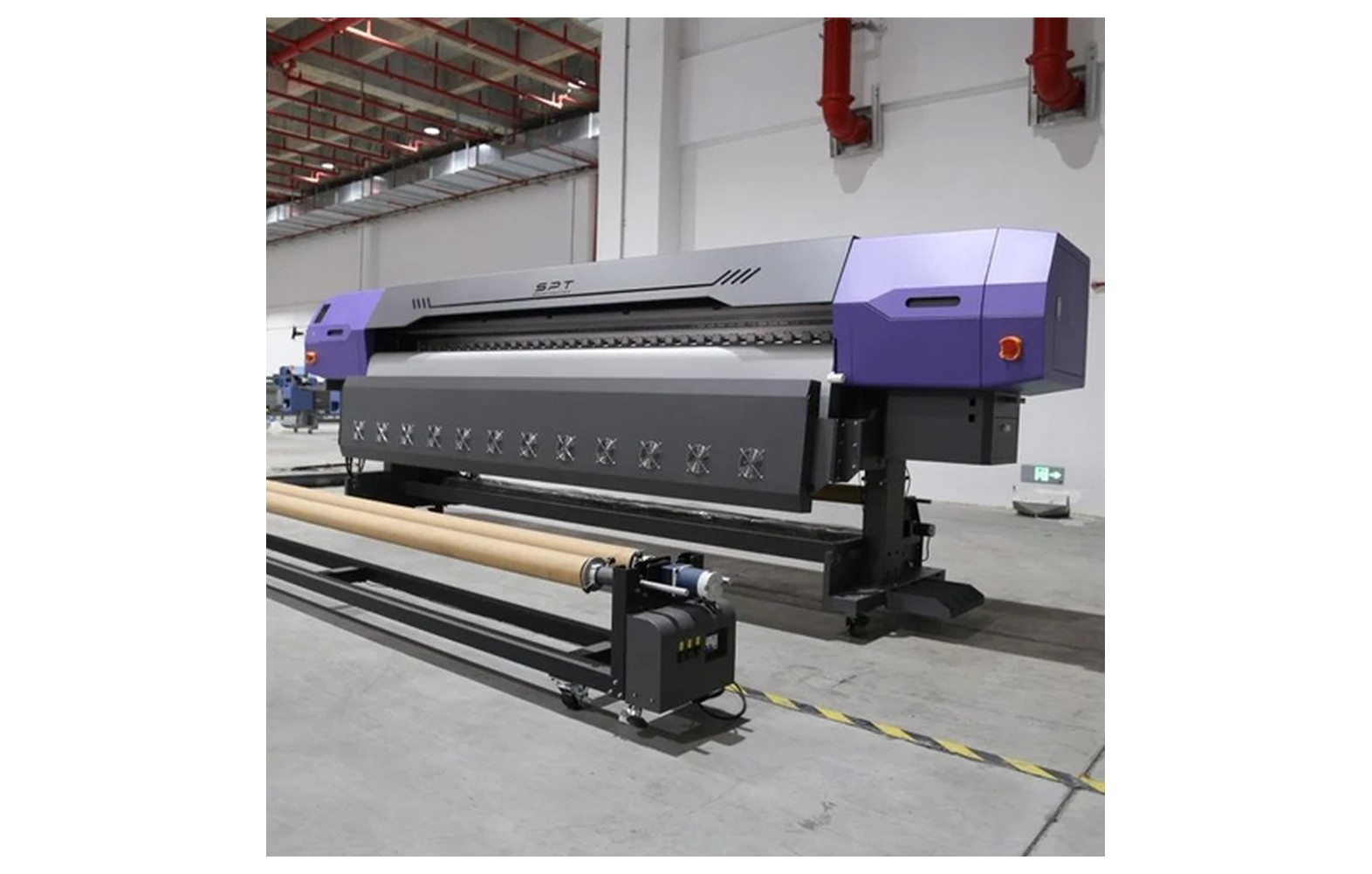
Direct answer: Roll media systems hold, feed and collect flexible material while coordinating its movement with the printer. Correct loading, tension and alignment depend on the machine and substrate; a take-up reel does not replace the printer feed system.
Engineering Principles and Components
| Topic | Function | Practical check |
|---|---|---|
| Supply roll | Provides the flexible substrate to the machine. | Check supported core, width, weight and loading orientation. |
| Feed rollers | Advance media under control of the printer. | Check seating and approved roller-pressure settings. |
| Tension control | Helps maintain suitable web behaviour. | Follow media and printer guidance; do not stretch or crease stock. |
| Take-up reel | Collects printed media where installed. | Confirm wind direction, tracking and compatibility with the job. |
Practical Shop Checklist
- Inspect the roll for damage, contamination and uneven winding.
- Use the manufacturer loading and edge-clearance procedure.
- Run the approved feed calibration for the media.
- Monitor long runs; stop safely for skew, creasing or head-clearance issues.
Why Media Handling Is Part of Print Quality
In a roll-to-roll printer, a flexible substrate must move through the print area in a controlled way. The printhead deposits ink while the controller coordinates carriage motion and media advance. If the material shifts, stretches, wrinkles or advances inconsistently, even a healthy printhead can produce an unacceptable result.
The media path is a complete system. The supply roll, loading hardware, rollers, platen, sensors and optional take-up reel all have roles, but their arrangement differs by manufacturer. A take-up unit collects material after printing; it is not automatically the device responsible for measuring every feed advance.
This guide explains the engineering concepts and safe operator checks. It does not replace the printer manual. Moving rollers, electrical equipment, heated surfaces and heavy rolls can be hazardous. Use approved loading equipment, keep guards in place and involve trained personnel for restricted service.
The Basic Roll-to-Roll Media Path
A typical roll is supported on a spindle, shaft or other manufacturer-designed holder. The substrate travels from the supply roll through a defined path, across a print platen and out of the printer. Feed or pinch rollers help control movement according to the machine design. Some printers use a take-up reel to wind finished media onto another core.
Not every machine has the same components. Some use different roller arrangements, media guides, sensors, heaters or tension controls. The supported width, roll weight, core size and loading orientation are model specific. Confirm the actual limitations before installing a roll.
As the printer builds the image, the media advance must be coordinated with the print mode. The actual distance and timing are controlled by the machine. A calibration procedure can help assess advance for a given substrate and mode, but it does not compensate for an incorrectly loaded or damaged roll.
Supply Roll, Core and Loading Direction
The supply roll must be supported securely using the hardware specified for the printer. Check the roll’s width, weight, core size and printable side against both the media and equipment documentation. A roll that is outside the specified capacity can create a handling or machine hazard.
Inspect the material before loading. A damaged core, telescoped roll, uneven winding, creased edges or contamination can cause tracking problems. If the roll is heavy, use the lifting method required by the site and equipment supplier. Do not place hands near pinch points or rely on an improvised support.
Loading orientation matters because the printable side and winding direction vary among products. Follow the media label and printer manual. After loading, verify the manufacturer’s alignment marks and media edge position. Avoid assuming that a roll is square just because it appears centred at one point.
Feed Rollers and Pinch Rollers
Feed rollers move or support the material as specified by the printer. Pinch rollers press the media against part of the drive system in some designs. Their placement, number and pressure settings can be important for tracking and media handling, but not every printer offers the same adjustments.
Follow the manual for roller placement and any permitted pressure setting. Incorrect placement can contribute to skew, marks or inconsistent movement. Excessive pressure may damage some materials, while insufficient engagement may allow slipping. The correct setting depends on the printer and substrate, not on a universal rule.
Operators should clean only accessible components using the approved method and materials. Do not reach into moving rollers, remove covers or adjust internal drive mechanisms while the machine is operating. If a roller is damaged or a mechanical fault is suspected, stop and request qualified service.
The Platen and Print Zone
The platen supports material as it passes beneath the head. Some printers use suction or another manufacturer-designed feature to help hold media flat. A clean and correctly loaded print zone helps maintain the clearance and positioning intended by the machine, but it does not guarantee that every material will behave identically.
Wrinkles, curled edges, loose media or contamination can raise the substrate into the head path. A head strike can damage the head or other components. If material lifts or a fixture or edge threatens the carriage, stop safely and follow the manufacturer’s procedure. Do not push material into place while the printer is moving.
Check the permitted head height and media thickness using the actual machine documentation. A higher setting is not a universal solution for poor loading, and an excessively small gap can increase collision risk. Test the highest point of the material where the manual requires it.
What Media Tension Means
Tension is the pulling force acting on the web of material. A roll system must manage the material without creating excessive slack, stretching or wrinkling. Some equipment provides a tension setting or control system, while other designs manage the web differently. Consult the manufacturer’s instructions for the installed mechanism.
Too much pull may stretch or distort a susceptible substrate or cause other handling problems. Too little control may allow slack or tracking problems. These are possible effects, not a diagnostic rule for every printer. Material stiffness, weight, coating, roll condition and winding can also influence behaviour.
Do not change hidden service parameters or add weight, drag or improvised brakes to a roll. Ask the supplier for the correct setup if a material is difficult to handle. A qualified technician should investigate internal tension-control faults and electrical or mechanical repairs.
How a Take-Up Reel Works
A take-up reel collects printed media onto a core during or after printing, depending on the design and workflow. It can reduce manual handling on suitable long runs. A properly set up reel follows the printer’s instructions for the material path, core attachment, winding direction and any available tension control.
Take-up is not a substitute for correct loading and feed calibration. If the incoming roll is skewed or a substrate stretches, the output reel may wind unevenly even though the reel itself is functioning. Conversely, an incorrectly installed take-up core or attachment can create its own tracking problems.
Before a long unattended interval, follow the manufacturer’s monitoring guidance and confirm that the winding direction, clearance and attachment are correct. Do not touch a moving roll or reach into a pinch point. Stop safely if the web creases, tracks sideways or threatens the machine.
Wind Direction and Printed Surface
Some take-up systems support different winding directions. Whether ink faces inward or outward can affect how the finished roll contacts adjacent layers, and the appropriate choice depends on the ink, media, drying or curing process and equipment. Follow the relevant supplier instructions rather than applying the same direction to every job.
Do not assume that a print is ready to wind simply because it looks dry. The required handling and finishing conditions depend on the ink and process. Ask the supplier about safe winding, storage and downstream finishing for the exact product. If an application needs adhesion or durability performance, agree suitable tests separately.
Label the finished roll with the job, material, orientation and any relevant handling instruction. Store it according to the media and ink suppliers’ guidance. Avoid placing a fresh print against an unsuitable surface or packaging without confirming the process requirements.
Media Feed Calibration Explained
Media-feed calibration assesses how a printer advances material relative to its intended movement. An incorrect advance can contribute to visible horizontal banding or dimensional inconsistency, but these symptoms have other possible causes. Use the test pattern and procedure supplied for the exact machine.
Calibration should be performed under the conditions specified by the manufacturer. The actual media, loading method, print mode and take-up arrangement may matter. Record the original setting before making an authorised adjustment, print the required test, select or enter the result according to the manual and verify a new sample.
A nozzle check is a separate diagnostic tool. Missing or deflected nozzles can affect a print even when feed is correct. Similarly, head alignment and print-and-cut registration address different relationships. Do not change all settings at once or copy a calibration value from another printer.
Feed, Alignment and Registration: Different Checks
Feed calibration concerns how the material advances. Printhead alignment concerns how printed marks are placed relative to motion or other heads. Print-and-cut registration concerns the relationship between printed artwork and a compatible cutter’s path. A complete job can depend on all three.
If a long graphic gradually drifts away from a cut path, the workflow may involve material handling, calibration, cutter settings, marks, lamination or other factors. A single symptom does not establish which setting is wrong. Follow the documented sequence for the printer and cutter, using the actual media and finishing process.
Save the original print, mark direction of travel and record where the error appears. If an authorised adjustment is made, keep the original value and the resulting test. Seek qualified support when the manual’s user-level procedure does not resolve the issue.
Common Media-Handling Symptoms
| Symptom | Possible areas | Safe first response |
|---|---|---|
| Material tracks sideways | Loading, roll condition, roller placement or take-up setup | Stop safely and follow the manufacturer’s reloading procedure. |
| Wrinkles near the print zone | Media condition, loading, tension or environmental factors | Stop if head clearance is at risk; inspect only accessible areas. |
| Horizontal bands | Feed, nozzles, alignment, ink or print mode | Retain the sample and run the approved diagnostic checks. |
| Uneven take-up roll | Core alignment, attachment, loading or substrate behaviour | Stop and review the documented winding setup. |
| Marks on the material | Rollers, contamination, pressure or media handling | Compare with the manual and use approved cleaning or service guidance. |
| Material rises towards the head | Curled stock, wrinkles, loading or hold-down | Stop immediately using the safe procedure and correct before printing. |
These observations are not proof of a specific faulty component. A trained technician may need to investigate the drive, sensors or other internal parts. Do not force a roll or adjust a hidden mechanism to see if the symptom disappears.
A Step-by-Step Operator Workflow
- Check the job and media. Confirm the substrate product, printable side, width and roll condition. Verify that the printer supports its size and weight.
- Load using the manual. Follow the specified media path, core support, guides and roller placement. Use appropriate lifting assistance where required.
- Check clearance. Inspect for curled edges, loose material and wrinkles using the approved procedure. Do not reach into moving equipment.
- Select the correct preset. Use the documented RIP and media settings for the printer, ink and material. Record the mode and any take-up configuration.
- Set up take-up if needed. Attach the media and core according to the equipment instructions. Confirm wind direction and safe tracking.
- Run approved tests. Check nozzle condition and perform media-feed calibration if the manufacturer directs it for this setup. Record any authorised changes.
- Print a representative proof. Inspect banding, colour, position and tracking. For print-and-cut work, validate the entire workflow including any lamination.
- Monitor the run. Follow the manufacturer’s supervision guidance. Stop safely for skew, creasing, abnormal noise or a clearance hazard.
- Document the result. Keep the approved sample, settings and material details for repeat jobs. Record defects and service actions.
Example: Skew During a Long Signage Job
A shop loads a roll for a long sign and notices the media drifting to one side. The operator stops the machine safely and keeps the initial sample. They check the roll condition, core support, media path and roller placement using the printer manual. If a take-up unit is installed, they review its core attachment and wind direction as instructed.
The operator reloads only as authorised and prints a short test before resuming. If the drift persists, the shop contacts service and provides the material details, loading observations and samples. The example does not prove that the take-up reel or rollers caused the skew; it shows how to gather evidence without making multiple unrecorded adjustments.
Example: Banding After Changing Material
A printer produces acceptable output on one film, but a new approved substrate shows horizontal bands. The operator first records the new material, RIP preset and mode, then saves a nozzle check. If jetting is acceptable and the manual directs a feed test for the material, the operator performs the specified calibration and keeps the before-and-after prints.
If the defect remains, other factors such as alignment, ink delivery, print mode or the material itself may need investigation. The team does not assume a new feed value is suitable for every future roll. The approved proof and settings are stored with the job record.
Storage and Environmental Considerations
Media can change behaviour with storage and operating conditions. Follow the substrate and printer suppliers’ instructions for temperature, humidity, handling and acclimatisation. Protect rolls from damage, dust and contamination. Do not invent a single environmental range for every material and machine.
When repeatability matters, record the supplier, product and batch of the substrate. Two rolls described by the same generic name may differ in coating, stiffness or winding condition. If a new batch behaves differently, compare it with a retained sample and consult the supplier before changing several machine settings.
When to Contact Service
Escalate a persistent feed error, damaged roller, abnormal drive noise, sensor warning or a fault that requires guarded access. A head strike, electrical fault or leak also warrants a safe stop and qualified inspection. Do not adjust belt tension, sensors or internal motor controls without the manufacturer’s authorised procedure.
Provide the printer model, substrate, roll dimensions, print mode, error messages and labelled samples. Explain which operator-level checks and calibrations were already performed. Ask the technician to document the diagnosis, authorised repair and post-service test.
Related Guides
Continue with media feed calibration and registration, banding diagnosis and head height and strike prevention. Always follow the instructions for your particular printer and substrate.
Related Engineering Guides
Start with how a piezo printhead works and digital inkjet machine anatomy. For a machine-specific question, share your model on our contact page.
Frequently Asked Questions
Does every printer use a take-up reel?
No. It is model- and workflow-dependent, especially on roll systems.
Why does roll media skew?
Possible causes include loading alignment, damaged stock, rollers or tension. Diagnose using the machine procedure.
What is media tension?
It is the controlled pull in the media path. Required settings depend on the machine and substrate.
Can I use any roll width?
No. Check the machine’s supported width, weight and core specifications.
Does the take-up reel feed the media?
The printer feed controls media movement; the take-up system collects output as designed.
Should every job be left unattended?
No. Follow the supplier’s operating and safety requirements and monitor production.
How do I prevent a head strike?
Use approved loading and head-clearance checks and stop if media lifts or wrinkles.
